
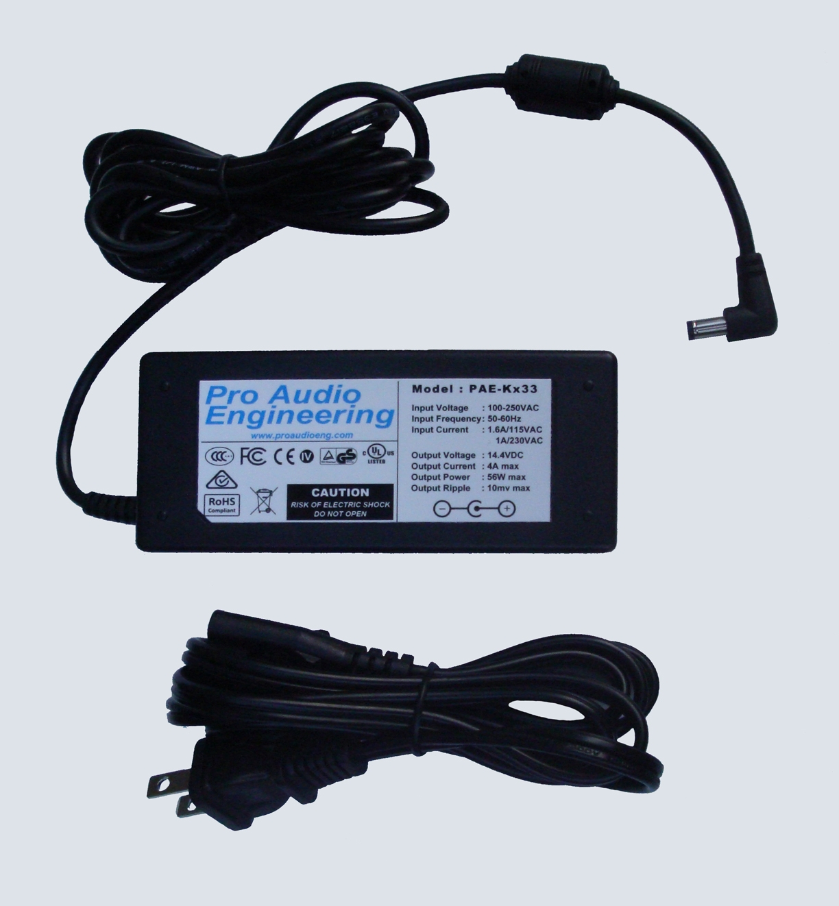
PAE-Kx33 14 V DC Supply. (click for new window)
PAE-Kx33 14 V 4 A DC Power Supply –
No adapter needed for Elecraft KX1,KX2,KX3,KH1
P/N: PAE-Kx33 Price: $59.90
Shipping Status: Immediate, In Stock
Adapter for the Yaesu FT-817/FT-818
P/N: 33-120 Price: $6.90
Shipping Status: Immediate, In Stock
Adapter for the Icom IC-705, Xiegu X6100
P/N: 33-140 Price: $6.90
Shipping Status: Immediate, In Stock
Adapter for the Xiegu G90
P/N: 33-155 Price: $9.90
Shipping Status: Immediate, In Stock
Adapter for the Lab599 TX-500
P/N: 33-175 Price: $12.90
Shipping Status: Immediate, In Stock
(Click on the “Accessories” tab to see our other adapters and accessories before checking out!)
We designed the Kx33 to address a very specific need: a small, light, easily portable high-power DC supply which has low AC input to DC output coupling. This is critical to minimize RFI due to common-mode currents often found with temporary antennas such as end feds or verticals.
The Kx33 was specifically designed for the needs of high-performance HF transceivers and communications equipment requiring a low-noise source of DC. It is perfect for use with any device designed to operate from DC 12-14 V at up to 4 A continuous, 5 A thermally limited. This allows the Kx33 to power conventional rigs up to 20 W.
This supply features an innovative design which inherently minimizes RFI. In addition the Kx33 features multiple filters to further reduce emissions, while paying particular attention to voltage regulation. The Kx33 has very low voltage undershoot and overshoot due to load transients in order to protect attached devices. The result is a power supply offering the small size and light weight advantages of a switching supply without the common disadvantages of RF noise, poor regulation and others.
Modern transceivers like the Elecraft™ KX2/3, Icom™ IC-705 and the Xiegu™ G90 raise the bar for portable HF performance, being able to fit a no-compromise station into a small shoulder bag or backpack is incredible! One piece of kit necessary for portable operation which has been elusive until now has been a quality light-weight AC power supply. The PAE-Kx33 is the first compact, lightweight AC-line operated switching power supply specifically designed to perform at the level required by these rigs.
Linear supplies can be very RF quiet, however dragging around a mains-powered linear supply capable of a true 4-5 A 14 VDC output is a problem, they are too big and heavy for truly portable use. Check out the size, weight and cost of just the 50-60 Hz 60 VA transformer some time! Like many KX2/KX3 owners we had been trying various small switching supplies not intended for communications use, and while they can be very small and light, they usually cause RF interference. As a result we often just used the supply to charge the internal batteries and unplugged it to operate, and with some rigs this will limit the output power.
The PAE-Kx33 was designed specifically to address all of these specific concerns of the HF rig owner, and features:
- Innovative switching topology to minimize RF interference and optimize efficiency.
- Extensive input and output filtering to ensure absolute minimum conducted and radiated RF.
- Carefully designed regulation to minimize and load-induced voltage variation.
- Less than a pound weight including AC cord to maximize portability.
- DC output is nominally 14 V (see Specifications) at up to 5 A.
- Supply will enable correct operation of the Elecraft KXBC3 Battery Charger.
- Correct right-angle 5.5 mm x 2.1 mm DC power plug as specified by Elecraft™ and others.
- Works perfectly with the Elecraft™ K1, K2-10*, K3-10, KX1, KX2, KX3, as well as the ELAD FDM Duo. With optional plug adapters sold here it is perfect for the Icom IC-705, Xiegu G90, Yaesu FT-817/818, Flex 1500, Ten-Tec 506 Rebel, and others.
- Supplied with standard US AC cordset (see Specifications for details).
- Lower noise and more output current capacity = better value than both competing and more expensive supplies.
- In addition to 100% testing at the factory, every unit is tested for no and full load voltage and RF spectral output immediately before shipping to you.
* – K2/10 with battery please read additional information here.
Input Voltage: AC 100 V to 240 V.
Input Current: AC 1.6 A peak at turn-on, 0.7 A max at 100 V input full-load, 0.3 A max at 240 V full-load.
Input Frequency: 50-60 Hz
Output Voltage (+/- 0.1 V)@ plug: DC 14.4 V no load, 14.2 V 0.2 A load, 14.0 V at 2.5A load, 13.8 V at 4 A load.
Voltage as displayed in the KX3 (+/- 0.1 V including internal KX3 drop): DC 14.1V in receive at 0.2 A load, 13.6 V in transmit at 2.4 A load.
Output Current: 5A maximum 60 seconds minimum, thermally limited.
Maximum ripple: AC 10 mV, 1 MHz – 30 MHz.
EMI: Meets or exceeds EN55022 Class B standards.
Efficiency 82% minimum @ => 200 ma load.
Protection: over-voltage, over-current, over-temperature, short-circuit.
MBTF: >50,000 hours.
Approvals: FCC, GS, TUV, CE, PSE, KC, SAA, CCC
Dimensions (excluding cables): 2″ x 1.25″ x 4.5″ (50 mm x 32 mm x 114 mm)
Cable Lengths: AC cordset – 60″ (1.5 m), DC supply cable – 80″ (2 m)
Output DC plug: 5.5 mm OD x 2.1 mm ID x 10 mm long right-angle DC barrel plug.
Input AC Plug: The PAE-Kx33 AC Power Supply has a standard 2-pin figure-8 AC input jack commonly designated an IEC 60320-C7, or merely C7 jack, and is supplied world-wide with US standard 2-prong NEMA 1-15P to figure-8 C7 2-pin AC line cord:
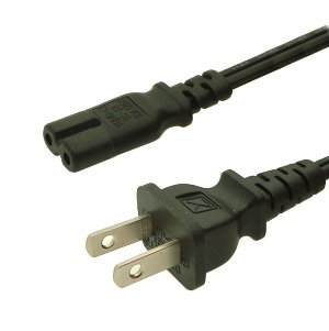
Supplied NEMA 1-15P to IEC C7 cordset
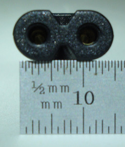
Figure-8 C7 AC plug
Due to the multiplicity of different AC plugs worldwide, we cannot stock other cordsets.
Adapters are readily available worldwide to fit the supplied cordset. Alternatively the purchaser can find a standard figure-8 2-pin cordset with the correct plug for their region.
The supplied cordset can also be modified by attaching the correct plug for the region.
Weight: supply: 9.3 oz (264 g), AC cord: 3 oz (85 g), total: 12.3 oz (349 g)
Warranty: 1 year from date of purchase. Read all Warranty details here.
There are several routes by which an AC line operated power supply can add noise to your transceiver:
- Conducting power supply RFI directly via the DC power jack (transverse mode).
- Conducting AC line noise through the supply to the DC power jack.
- Radiating switching noise from either the AC or DC power supply cables to the antenna/feedline.
- The most often occurring source: conduction of common-mode antenna currents through the power supply to the AC line. This is due to imbalances in the antenna system and can be remedied by installing a common-mode choke either in the antenna line or on the DC power cable.
- There is also a possible increase in the noise floor due to coupling through the power supply to the AC line which is not necessarily added noise; it is actual signal increase of band noise due to increased antenna efficiency thanks to the ground counterpoise of the AC wiring. This effect is more pronounced on 160M and 80M, where many antenna counterpoises are relatively high impedance compared to the AC distribution system.
In order to quantify these effects we tested the new PAE-Kx33 along with several popular small switching supplies, a large linear supply and a large AGM (Absorbed Gas Mat) lead-acid battery. The switching supplies tested were all supplies commonly used in the ham community for QRP rig powering, and were suggested by fellow hams. To get results mirroring actual QRP usage as closely as possible, the measurements were taken directly from an Elecraft KX3’s DC power jack with a small DC power splitter PCB. For the waveform and spectral analysis the DC power jack was coupled to the spectrum analyzer by three paralleled 0.1uF XR7 capacitors (DC-blocking 10KHz HP filter into 50Ω) to a 3′ piece of 50Ω RG-393 for the AC measurements. Both the Tek scope and spectrum analyzer were then terminated in 50Ω to reduce overshoot and ringing. Here is an image of the DC power sampling test jig:
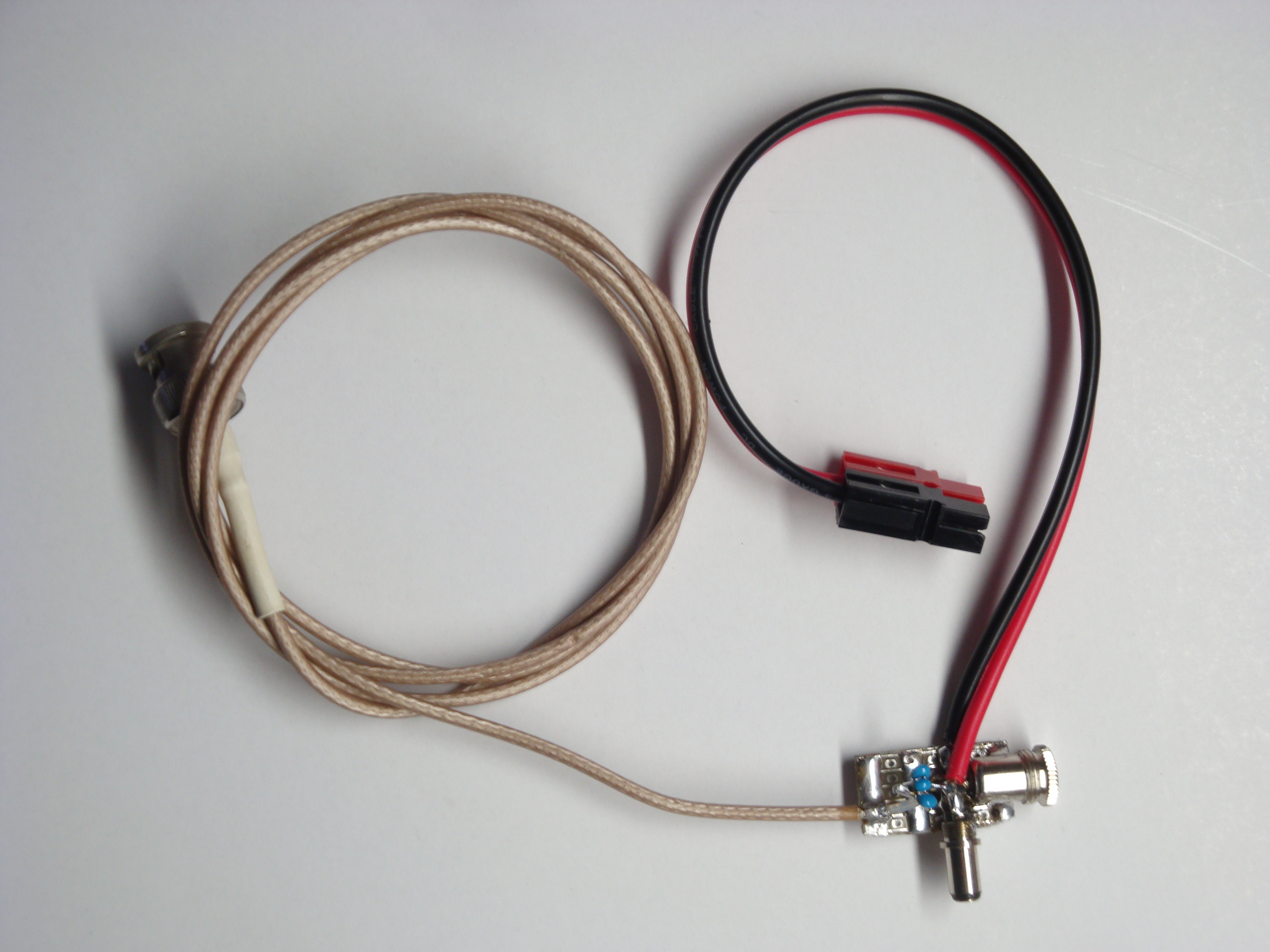
KX3 power breakout pcb (click for new window)
In order to quantify the quality of the DC power output we tested for these parameters:
1) DC voltage, KX3 off using an HP 3468 DVM.
This shows the quiescent voltage of the power supply with no load.
2) DC voltage, KX3 in receive using an HP 3468 DVM.
This is the voltage at the DC Power jack with the KX3 in receive drawing ~200 mA.
3) DC voltage, KX3 in transmit using an HP 3468 DVM.
This voltage is measured at the DC power jack with the KX3 in transmit on 28.100MHz into a 50Ω dummy load at 10W drawing ~2.7 A
4) Capacitance from the AC line to the DC output ground using an HP4263B LCR Meter @ 100 KHz..
The lower the capacitance the less AC power line noise is conducted to the KX3., also minimizes conduction of common-mode currents from the antenna system to the AC power line.
5) Ripple P-P amplitude as viewed on a connected directly to the KX3’s DC power jack using a Tektronix 2465 350 MHz oscilloscope.
This is AC riding on the DC voltage from the power supply, the lower the ripple, the less noise is conducted into the KX3. Note the vertical scale which was changed to optimally view the waveform.
6) The ripple RMS voltage , 10 MHz BW using an HP400EL AC RMS Voltmeter.
The AC voltage ripple on the DC as read on a wide-bandwidth meter.
7) Spectral capture of the increase in RF from 10 KHz to 10 MHz using a Tektronix 2712 Spectrum Analyzer, and comparing against the spectrum powered by an external battery.
The Vertical Scale is 10 dB/division, and it has been set so that the top line is -30 dBm. The AGM battery and Astron linear supply spectra were straight-forward sweep captures. All of the switching supplies spectrum analyses were displayed as the difference between the spectrum when the KX3 was powered by the battery and the switcher being tested, normalized to the middle line of the screen. In other words, if the switcher was totally quiet, the trace would be a straight line at the middle of the screen. The greater a deviation from this the more noise energy the switcher generates compared to the battery. We did this because as you will see, when powered by a battery the KX3 passes RF from its internal circuitry to the DC power jack. Because of this even a perfectly quiet supply would show some RF at the DC power jack. Since we were trying to see how quiet these switching supplies were relative to the battery, the displayed spectra is normalized to the battery’s receive spectra with an algebraic C=A-B analyzer function, C being the differential sweeps shown here, A being the raw spectra of the switchers, and B being the spectrum of the KX3 on a battery.
The Horizontal Scale is linear frequency and it is set to 1 MHz/division, so the left most vertical line is 0 Hz, the center line is 5 MHz, and the rightmost line is 10 MHz.
When looking at these spectra, keep in mind the majority of the ripple in the output of each supply is at the switching fundamental frequency, which for all the supplies tested is between 20 KHz and 100 KHz. This places the spike associated with the fundamental too close to 0 Hz to be seen in the screen shots below. Since it is not the fundamental but the harmonics and switching edge ΔV/ΔT spectra which wreak havoc with our HF ham bands, we set up to analyze the harmonics. The sweep is limited to 10 MHz, since the majority of interference caused by switching power supplies is below that frequency. 10 MHz is high enough to capture up to the 333rd harmonic of a 30 KHz supply, or 99th harmonic of a 100 KHz supply.
Although most of these switching supplies show an increase in output ripple at the higher current drawn by the KX3 in transmit, this is not usually a problem, since the receiver is muted. It can however, be a problem in a multi-operator contest or operation such as a dxpedition. To check this out we did a spectrum analysis from the battery with the KX3 in transmit @ 10 W, drawing ~2.5 A. This spectrum was then subtracted from each supplies individual spectra in the same manner as the receive testing, and the difference is displayed for each supply, normalized to the vertical center of the screen.
8) Current step response, between 0.200 A and 2 A using a Maynuo M9713 Electronic Load and monitoring with a Tektronix 2465 350 MHz oscilloscope and a DC nulling circuit.
This measurement shows the stability and response time of the voltage servo in the power supply regulator. Actually there is a lot of information encoded in this waveform:
a) Overshoot of the voltage regulator when transitioning from high current to low current.
b) Undershoot when transitioning from low current to high current.
c) Voltage Drop by comparing the voltage at 200 mA to the voltage at 2 A. This voltage drop is the sum of the internal regulation error and the voltage drop of the power supply DC cable, and the lengths differ, so no absolute conclusion can be made about the supply impedance.
d) Stability and bandwidth of the voltage servo as ringing in the transitions.
e) Relative RFI output at low and high currents.
Important notes:
The DC voltages stated are measured at the DC power jack of a KX3, not read from the internal KX3 voltmeter, which reads several tenths of a volt lower depending on current.
When reviewing the test results pay attention to the scaling! The oscilloscope sensitivity was set differently for each power supply in order to show detail about the ripple of that supply.
The current step waveforms were captured at the electronic load end of the manufacturer supplied DC cable, except for the battery and Astron supply which were connected by a 6 foot/1.8 meter piece of #12 x 2 cable.
The spectrum analyzer settings were straight captures for the battery and linear supply, and differential captures (read the “Testing” tab) for all the switchers, with the display normalized to the vertical center of the screen. A perfectly quiet supply would be a straight line at the center of the screen which is ~-95dBm.
Powersonic PS12180 AGM Lead-Acid Battery
DC Voltage no load: 13.1 V
DC Voltage receive: 13.0 V@0.2 A
DC Voltage transmit: 12.8 V@2.5 A
AC line to DC output capacitance: N/A
Maximum ripple amplitude: <200 uVp-p
Ripple+noise RMS voltage (10 MHz BW): <0.25 mV
1a) Powersonic AGM battery noise, KX3 off 2 mV/div. Less than 400 uV of noise which is the baseline for this test setup.
1b) Powersonic AGM battery + KX3 noise, KX3 on. The broadband noise increases to ~800 uV which is due to internal KX3 circuits.

1c) Powersonic AGM, current step between 0.2 A and 2 A
1d) Powersonic battery supply, KX3 off. (10 KHz-10 MHz) Average noise is around -95 dBm.

1e) Powersonic battery supply + KX3 ripple. (10 KHz-10 MHz) Noise from KX3 circuitry is at 2-2.5 MHz at ~-78 dBm.
Image 1a shows the noise of the test setup when powered by the Powersonic AGM battery, with the KX3 turned off, and 1b shows the contribution of the KX3’s internal circuitry when turned on. The 2 A to 0.2 A current step waveform in image 1c shows the ~12 mV of recovery after load removal typical of lead acid batteries. Image 1d is the spectrum at the DC power jack with the KX3 off at ~-95 dBm, the limit of the test setup and 1e is KX3 on, in receive drawing 0.2 A. The RF present is very low-level with a broad maxima of -78 dBm around 2-2.5 MHz, and comes from the KX3’s internal circuitry. This second spectrum in image 1e was the baseline for the rest of the spectral tests, and was electronically subtracted from each of the line-operated supply’s spectra in order to get the true added noise from each supply.
Astron RS-50M Linear Power Supply
DC Voltage no load: 13.2 V
DC Voltage receive: 13.1 V@0.2 A
DC Voltage transmit: 13.0 V@2.5 A
AC line to DC output capacitance: 1500pF
Maximum ripple amplitude: 5 mVp-p
Ripple+noise RMS voltage (10 MHz BW): 0.8 mV

2a) Astron linear supply noise, KX3 in receive 2 mV/div

2b) Astron linear supply response to a 2 A to 0.2 A current step with ~10 mV of overshoot.
2c) Astron linear supply response to a 25 A to .2 A current step.
2d) Astron linear supply + KX3 ripple spectrum (10 KHz-10 MHz)
Image 2a is the Astron linear power supply noise at the DC power jack, with the KX3 in receive drawing 0.2 A. The average ripple is very low and had intermittent spikes which were difficult to capture with the scope photo, most likely due to AC line coupled energy. The image in 2b is of the 2 A to 0.2 A current step, note the ringing most likely due to the inductance of the 6 foot 8 ga. cable between the supply and load. To see what the supply would do at higher currents we increased the load to 25 A, as shown in 2c. The droop at the higher current is most likely due to a capacitor at the output terminals which holds the voltage up for 30mS or so. As with operating off the battery, there are no outstanding spurs, but the noise level from 500 KHz to 2 MHz is about 6dB higher than that of the KX3 powered by the AGM battery as shown in 2d. This is probably due to a combination of regulator noise and coupling of power-line carried RF. The Astron linear supplies are an execution of an LM723 Application Note, and while the 723 is tried and fairly reliable, their performance has been eclipsed for many years, indeed the 723 is very noisy compared to modern regulators. There was no perceptible change to the sound of the noise floor compared to using the Powersonic AGM battery. Any additional noise with increased power draw would most likely be line harmonics which are masked near the 0 Hz Y-axis of the analyzer, so we did not perform a transmit spectrum analysis.
PAE-Kx33 Switching Power Supply
DC Voltage no load: 14.4 V
DC Voltage receive: 14.2 V@0.2 A
DC Voltage transmit: 14.0 V@2.5 A
AC line to DC output capacitance: <100 pF
Maximum ripple amplitude: 4 mVp-p
Ripple+noise RMS voltage (10 MHz BW): 0.95 mV
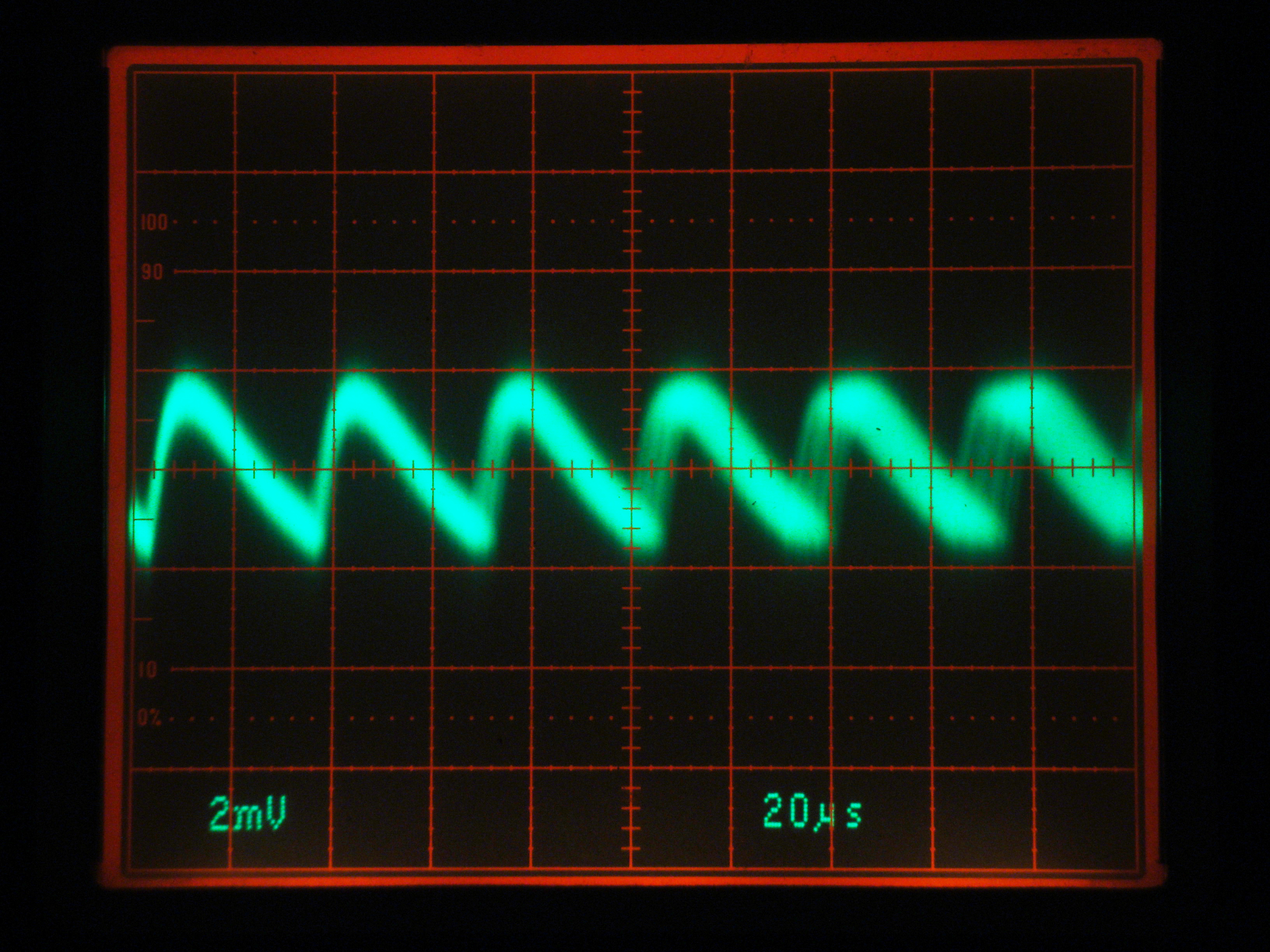
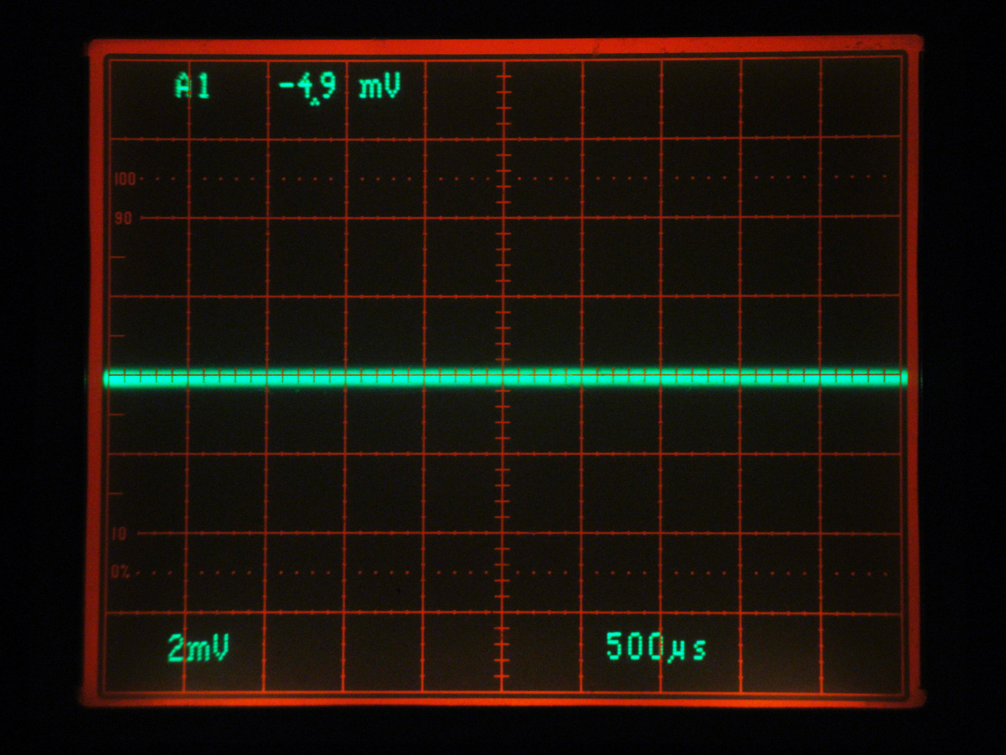
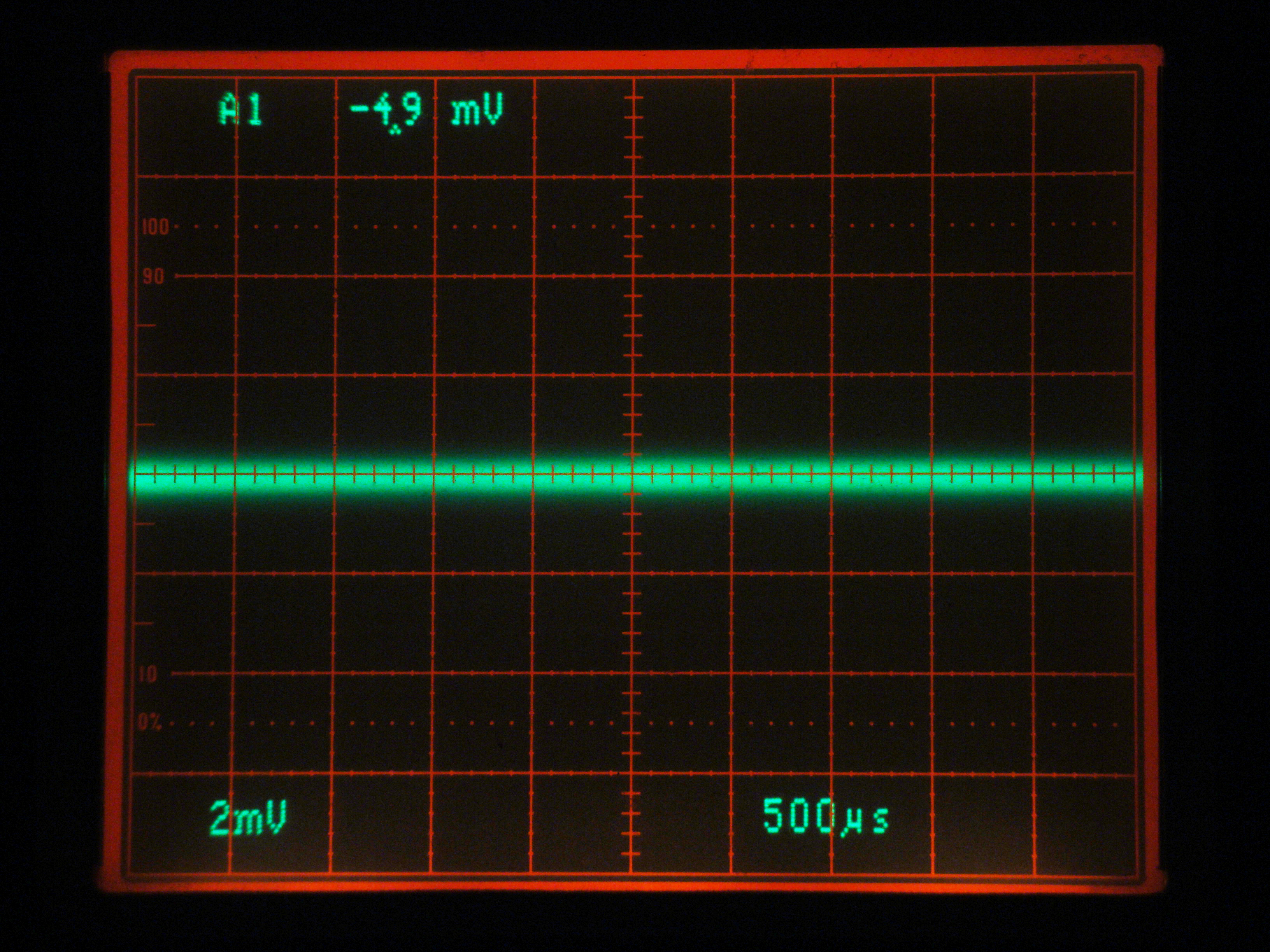
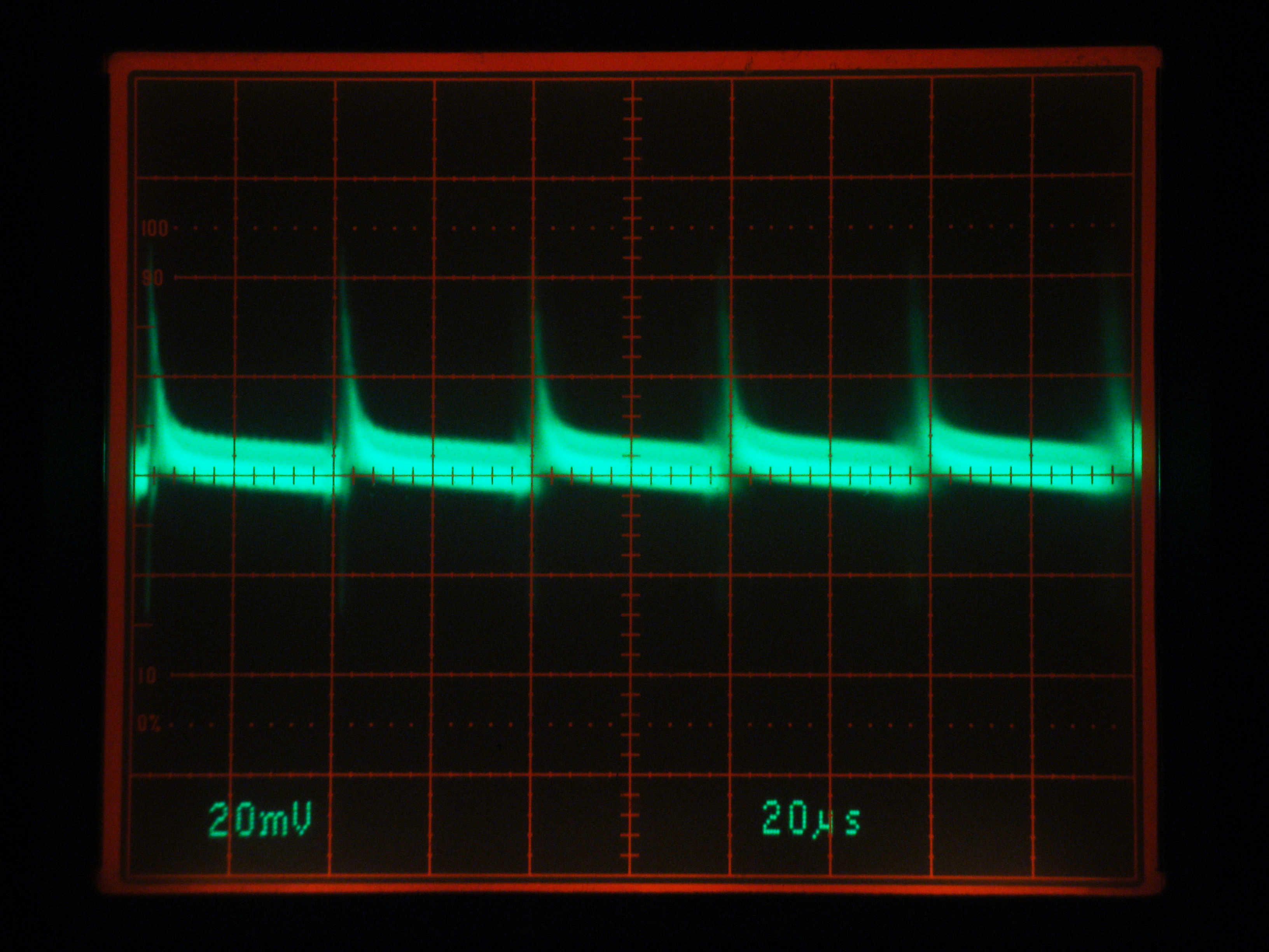
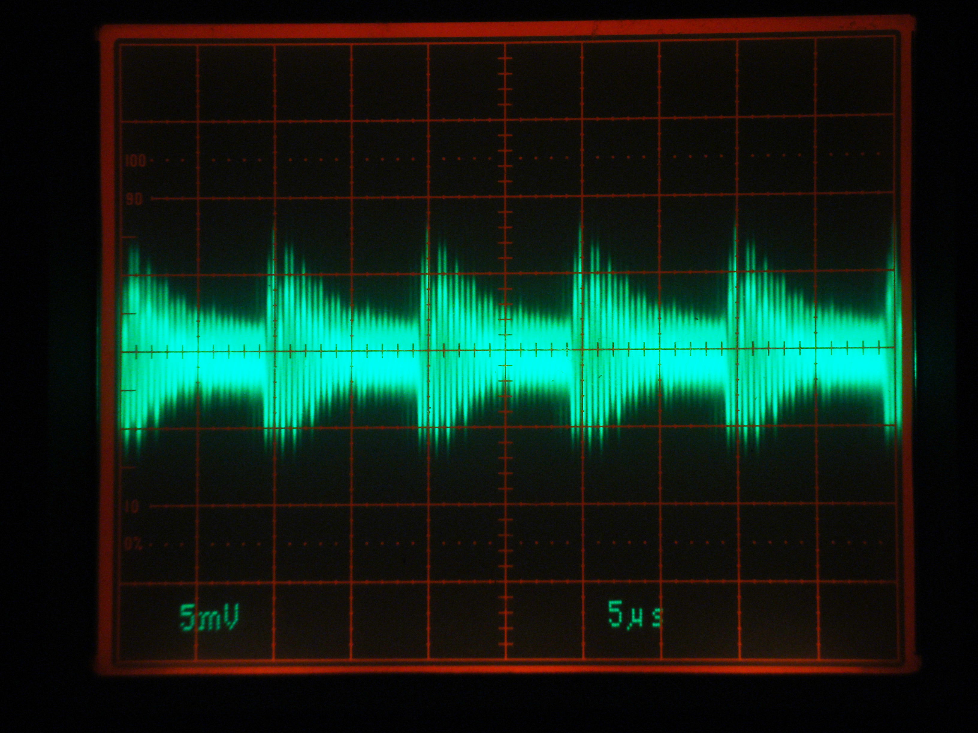
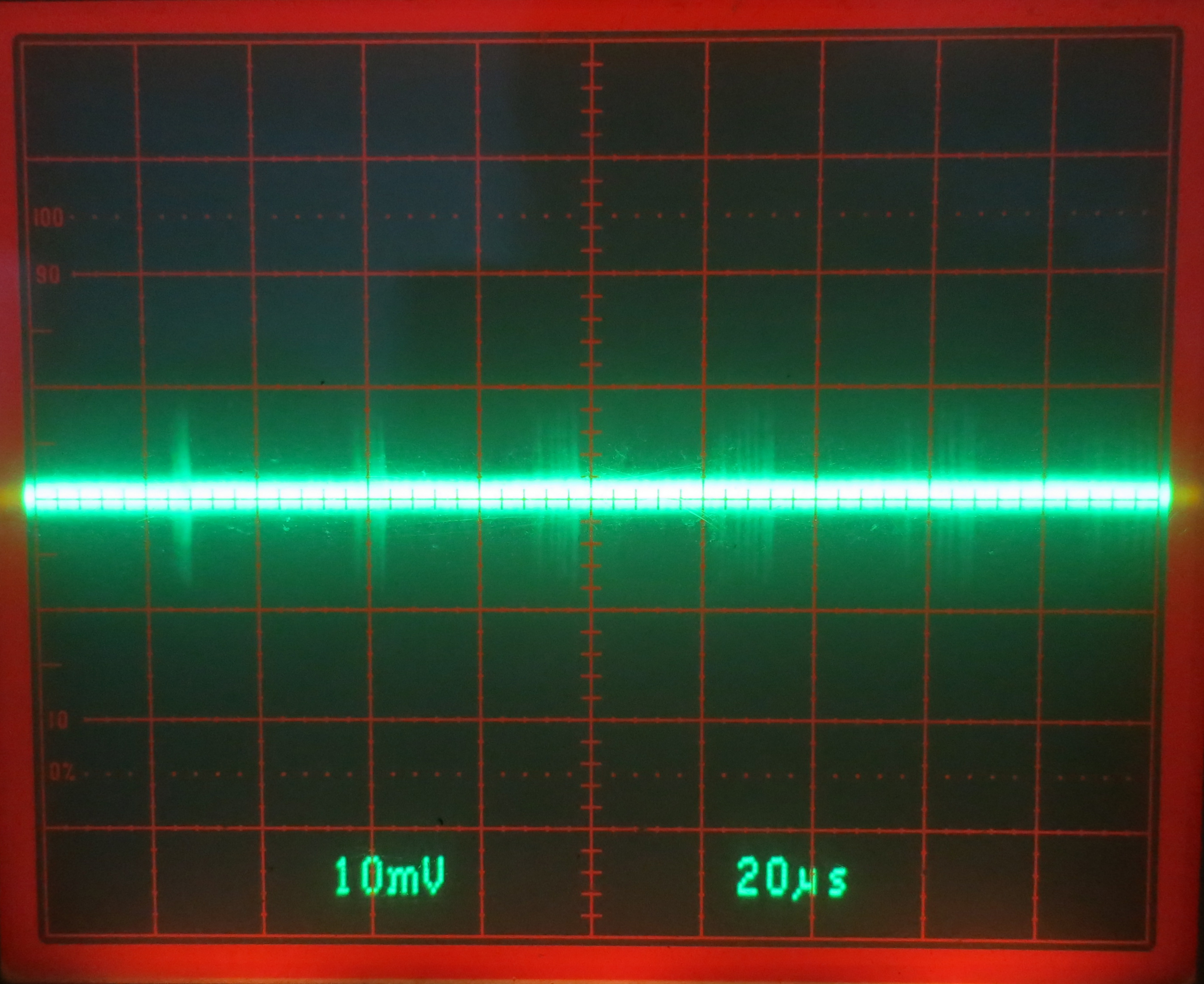
3a) PAE-Kx33 switching supply noise, KX3 in receive 2 mV/div, ~4 mV P-P of ripple.
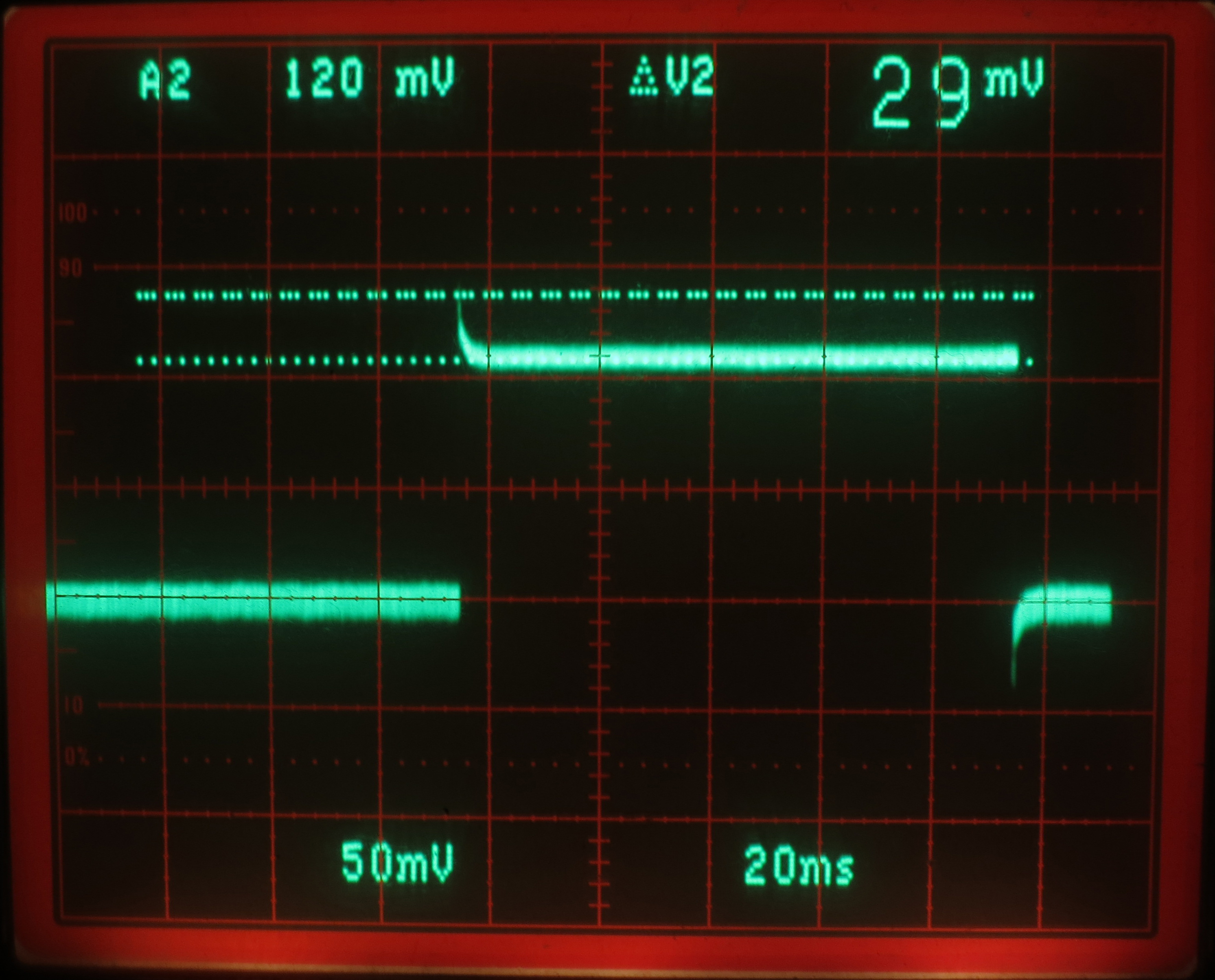
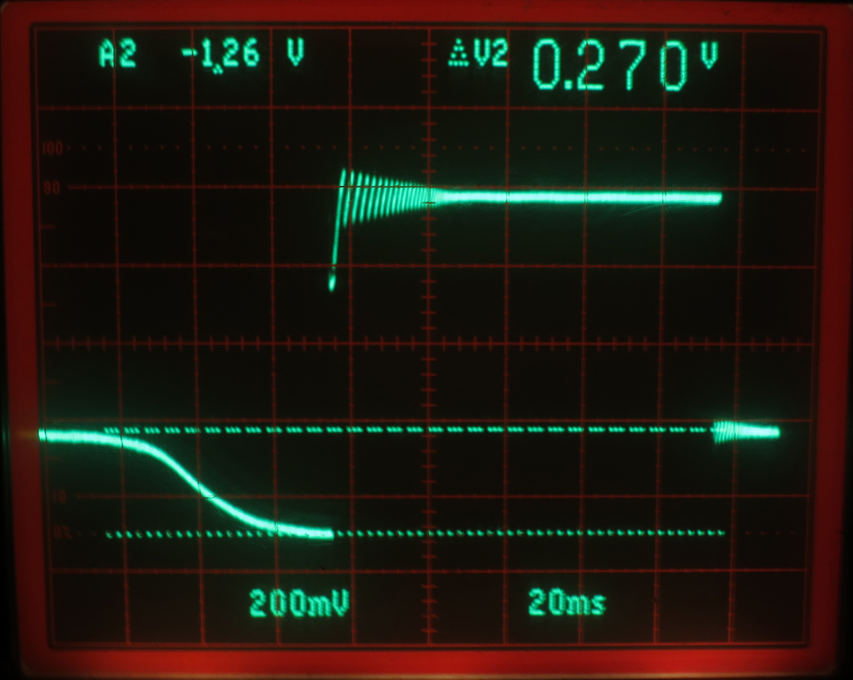
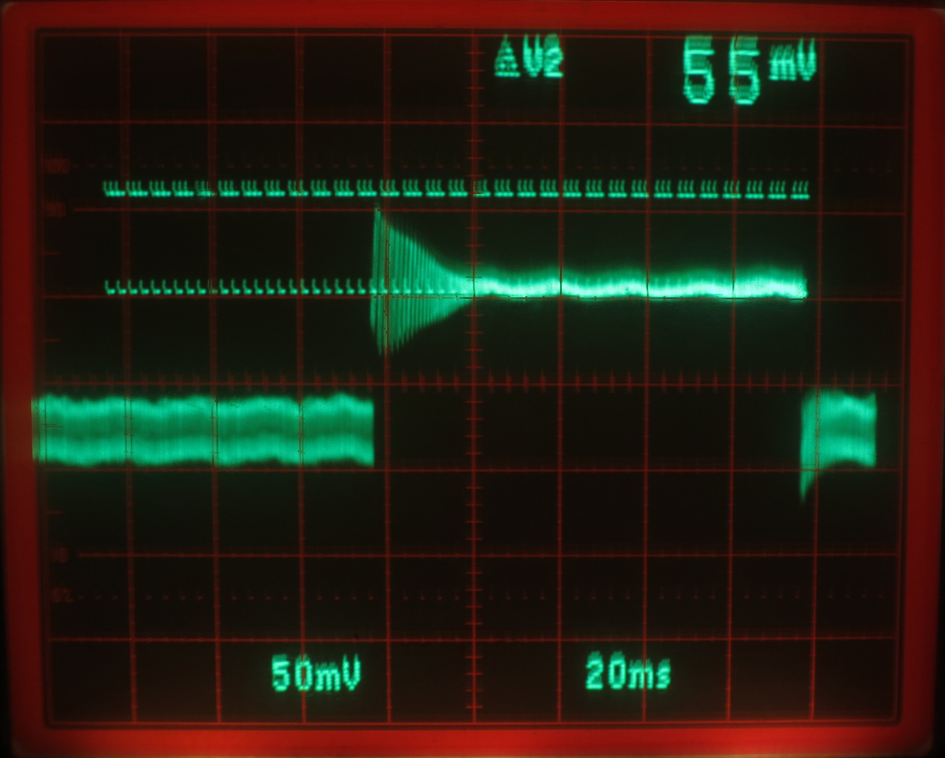
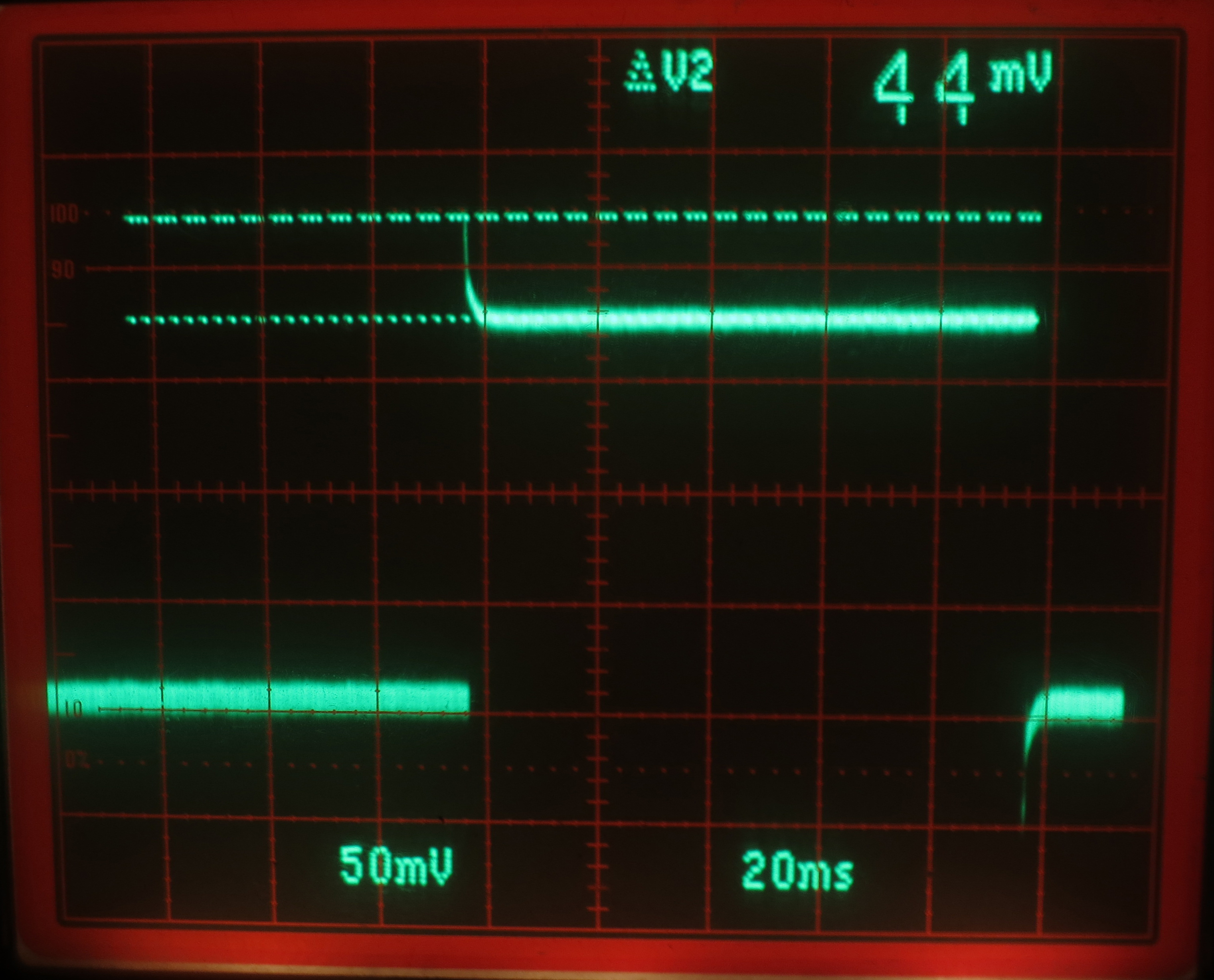
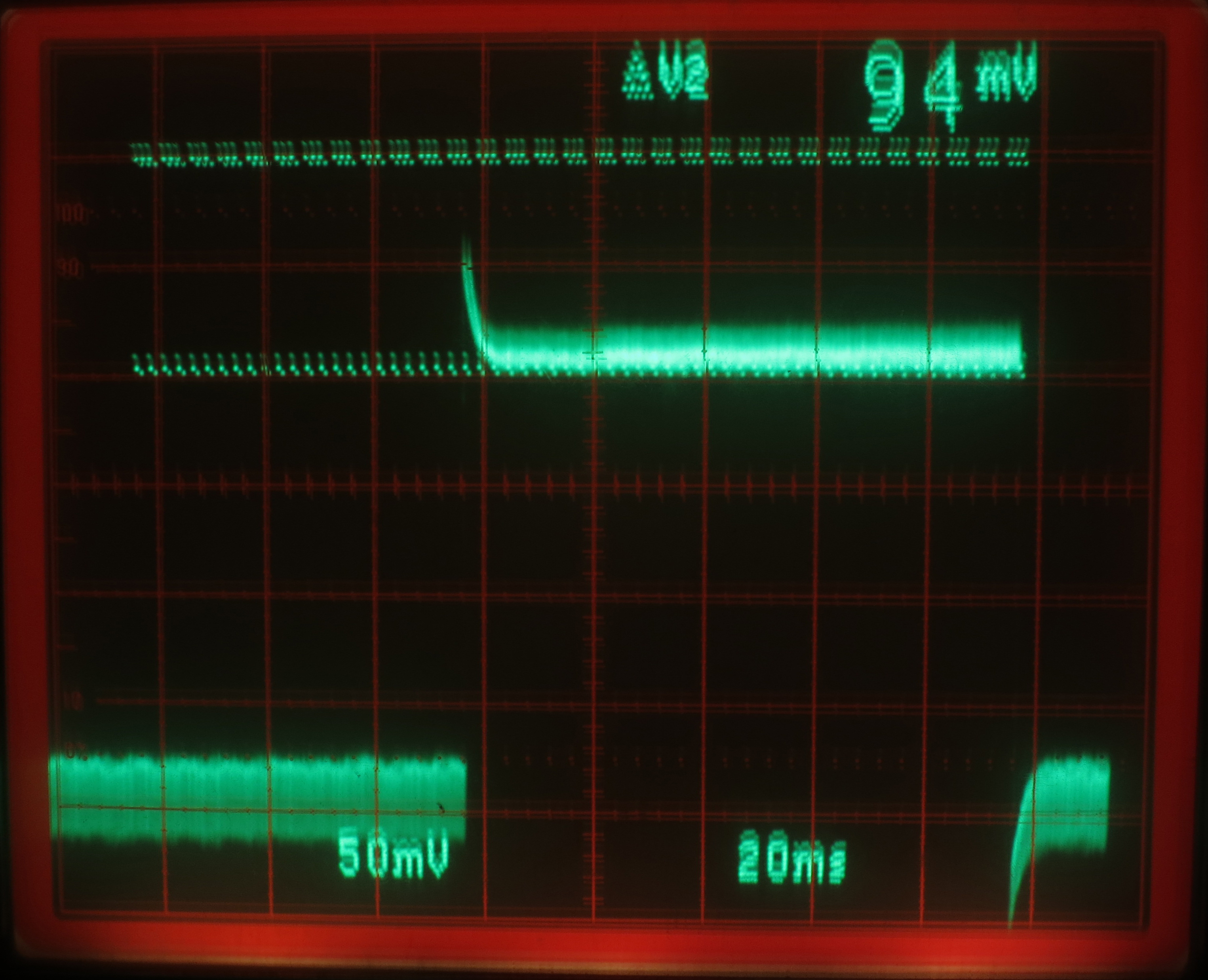
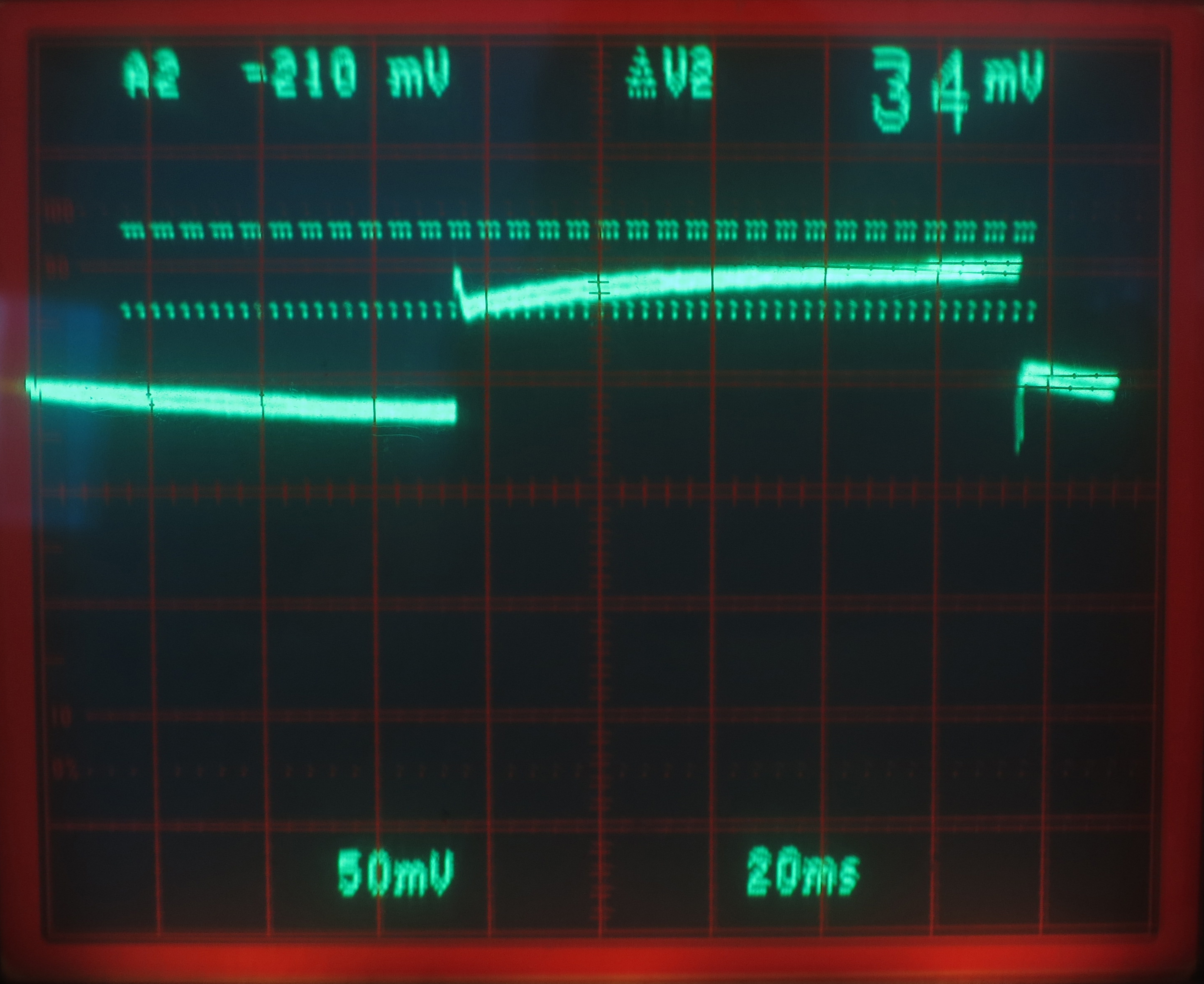
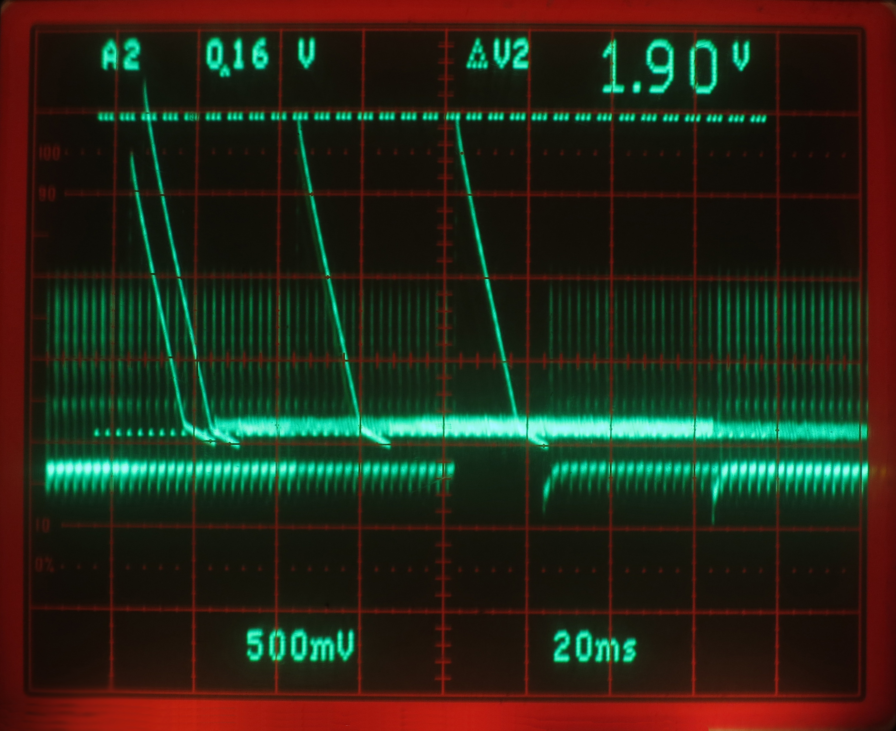
3b) PAE-Kx33 response to a 2 A to 0.2 A current step, ~29 mV of overshoot.

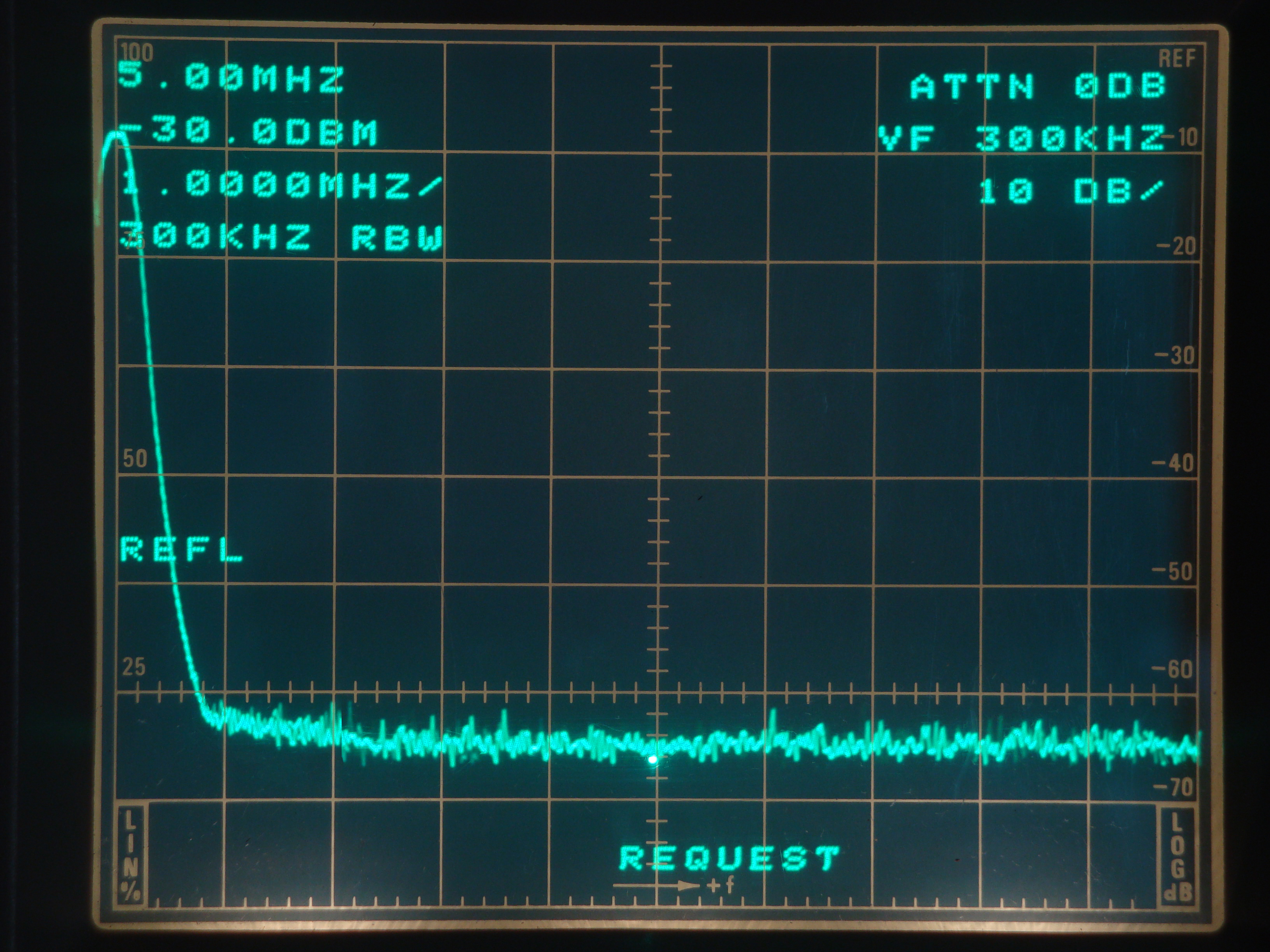
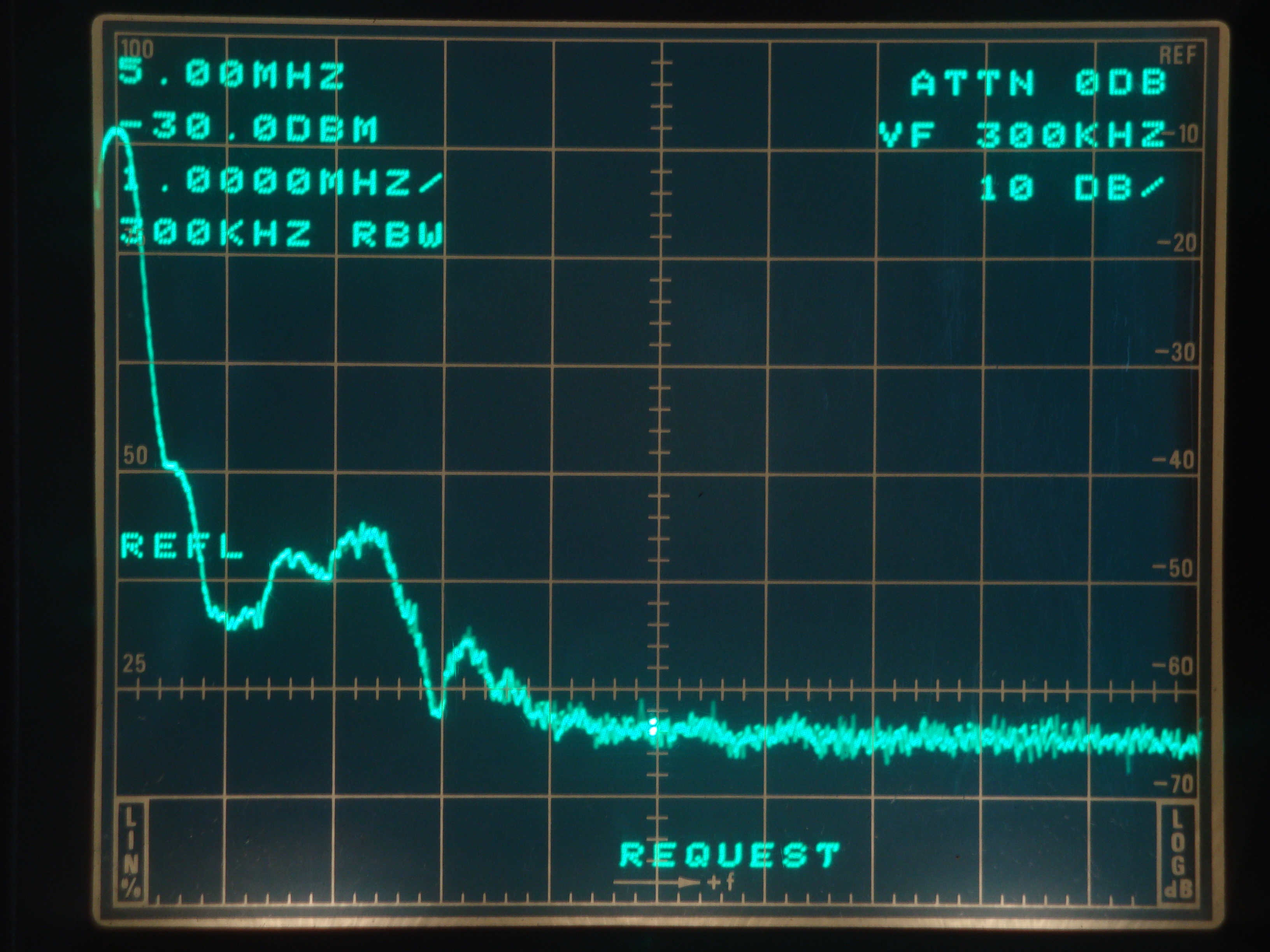
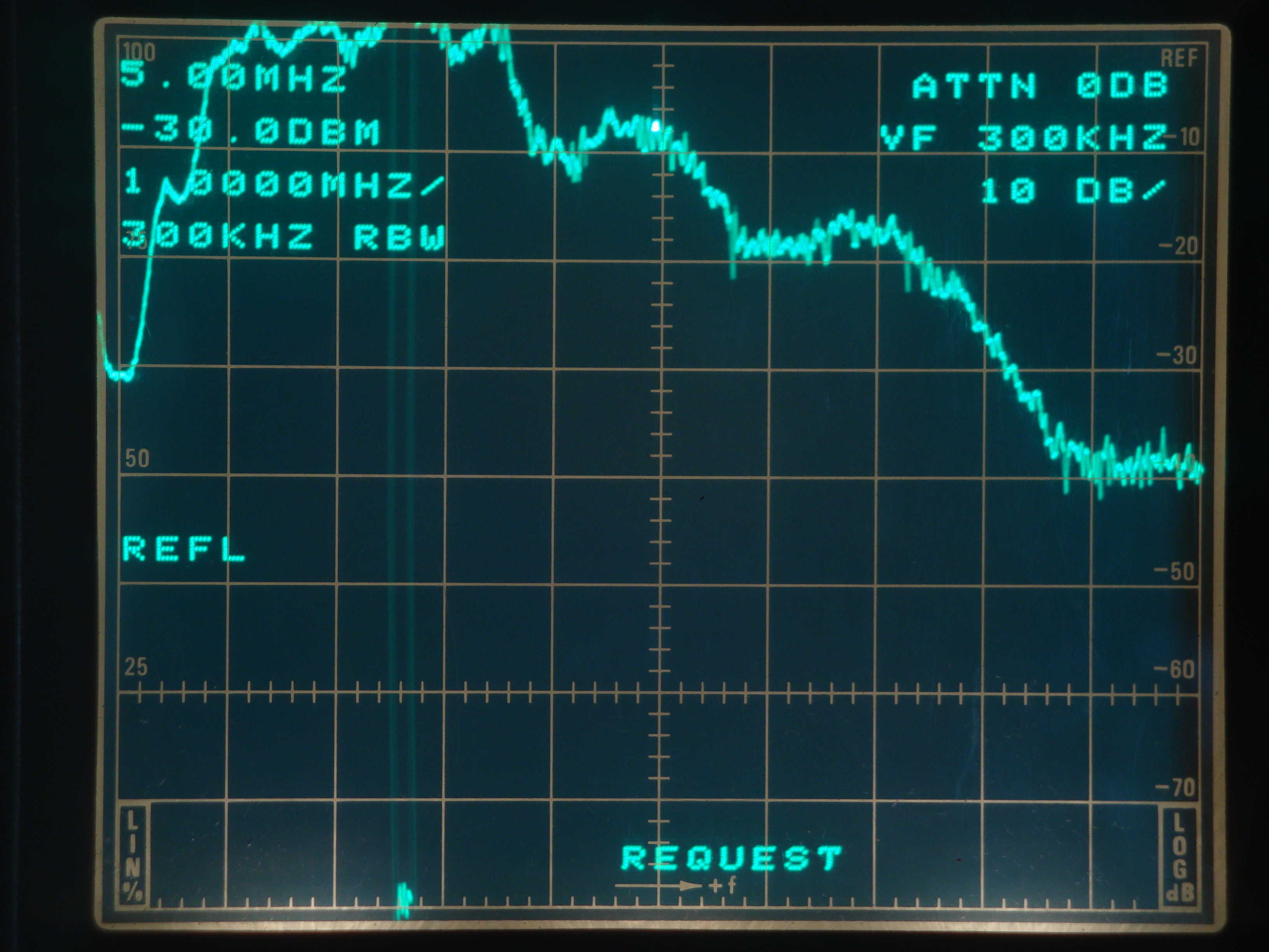
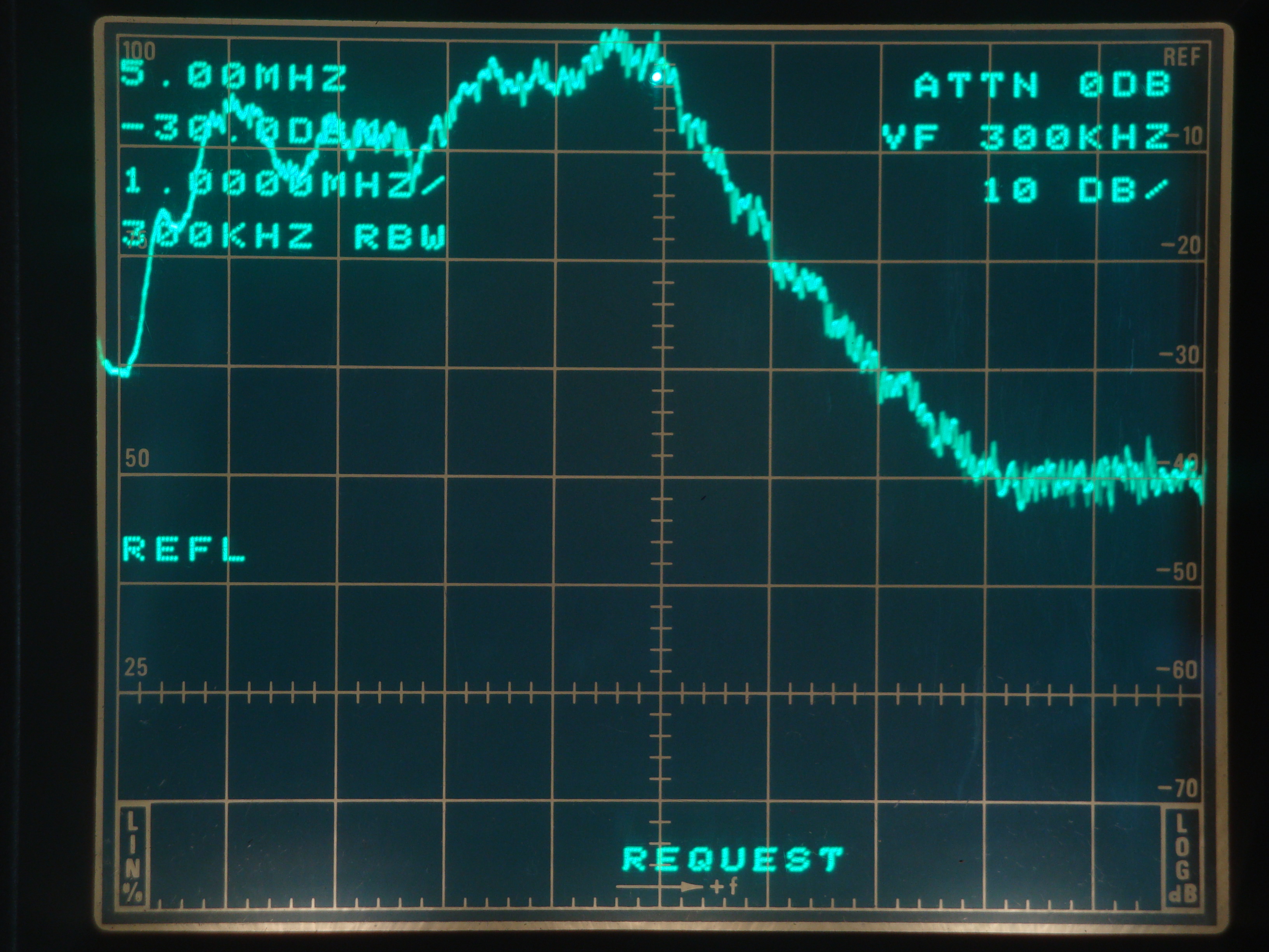
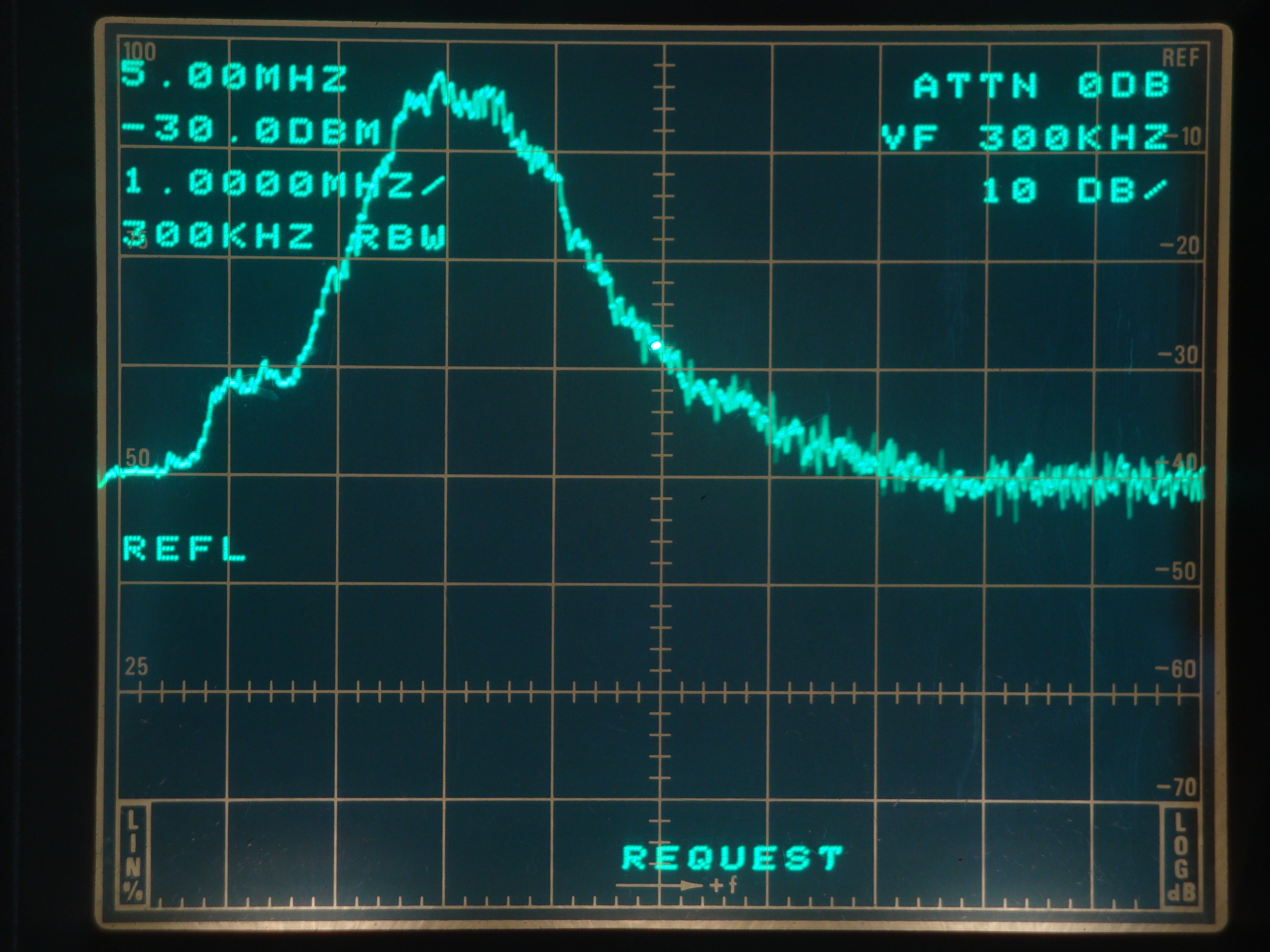
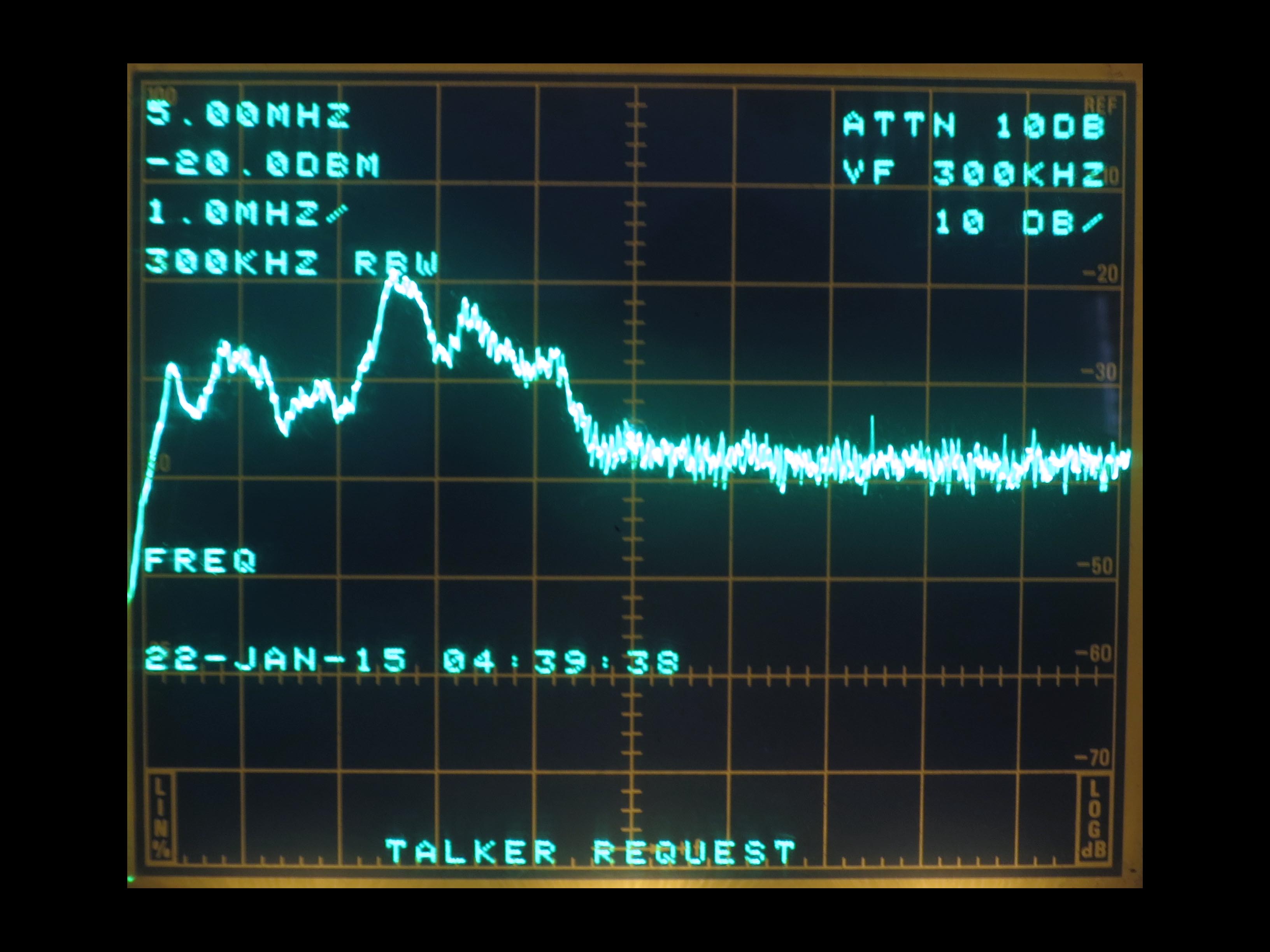
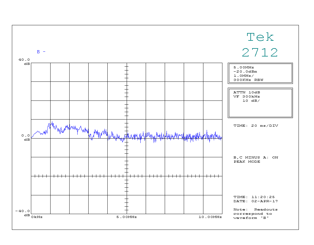
3c) PAE-Kx33 switching supply spectrum, KX3 in receive (10 KHz-10 MHz)
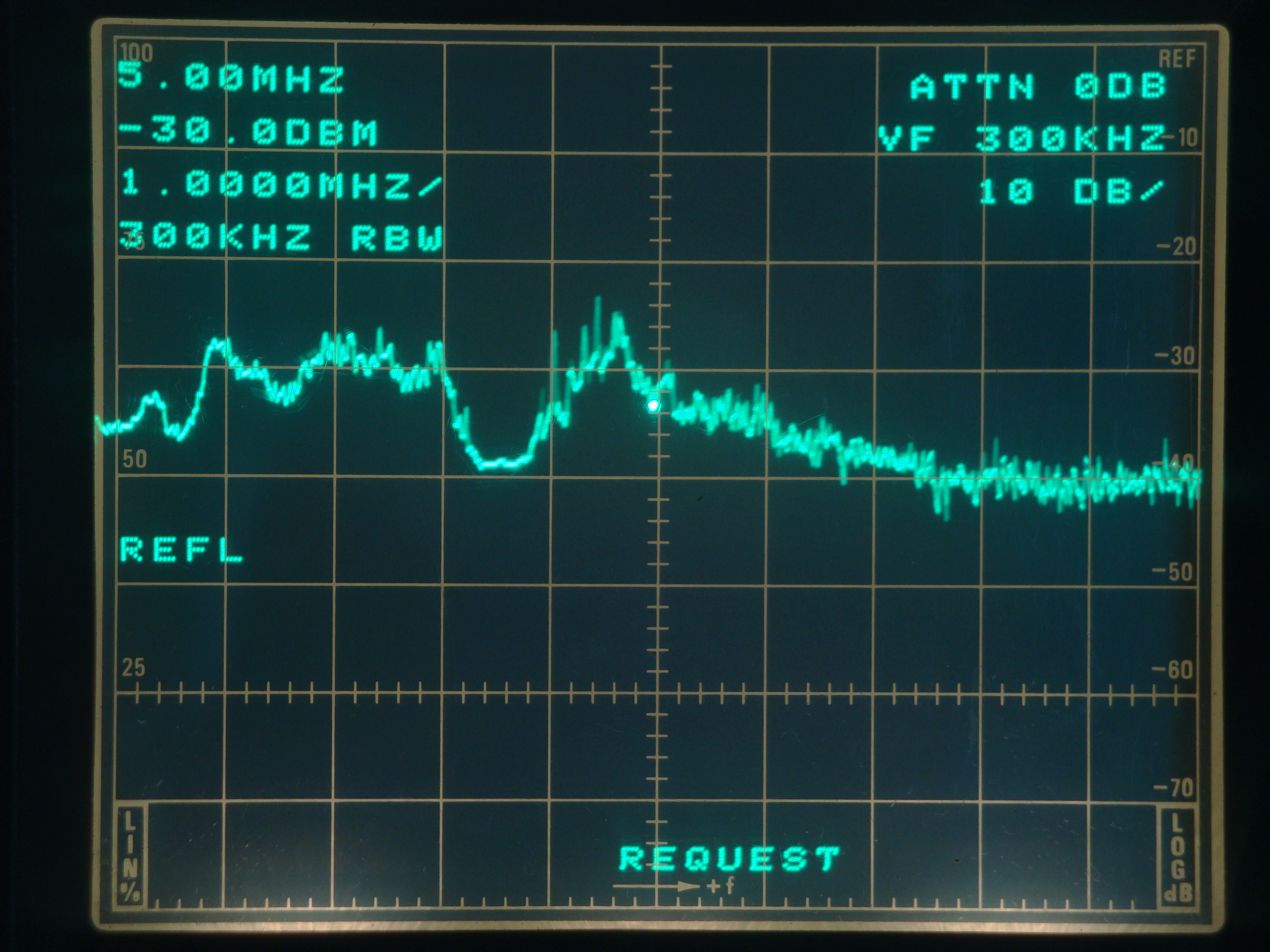
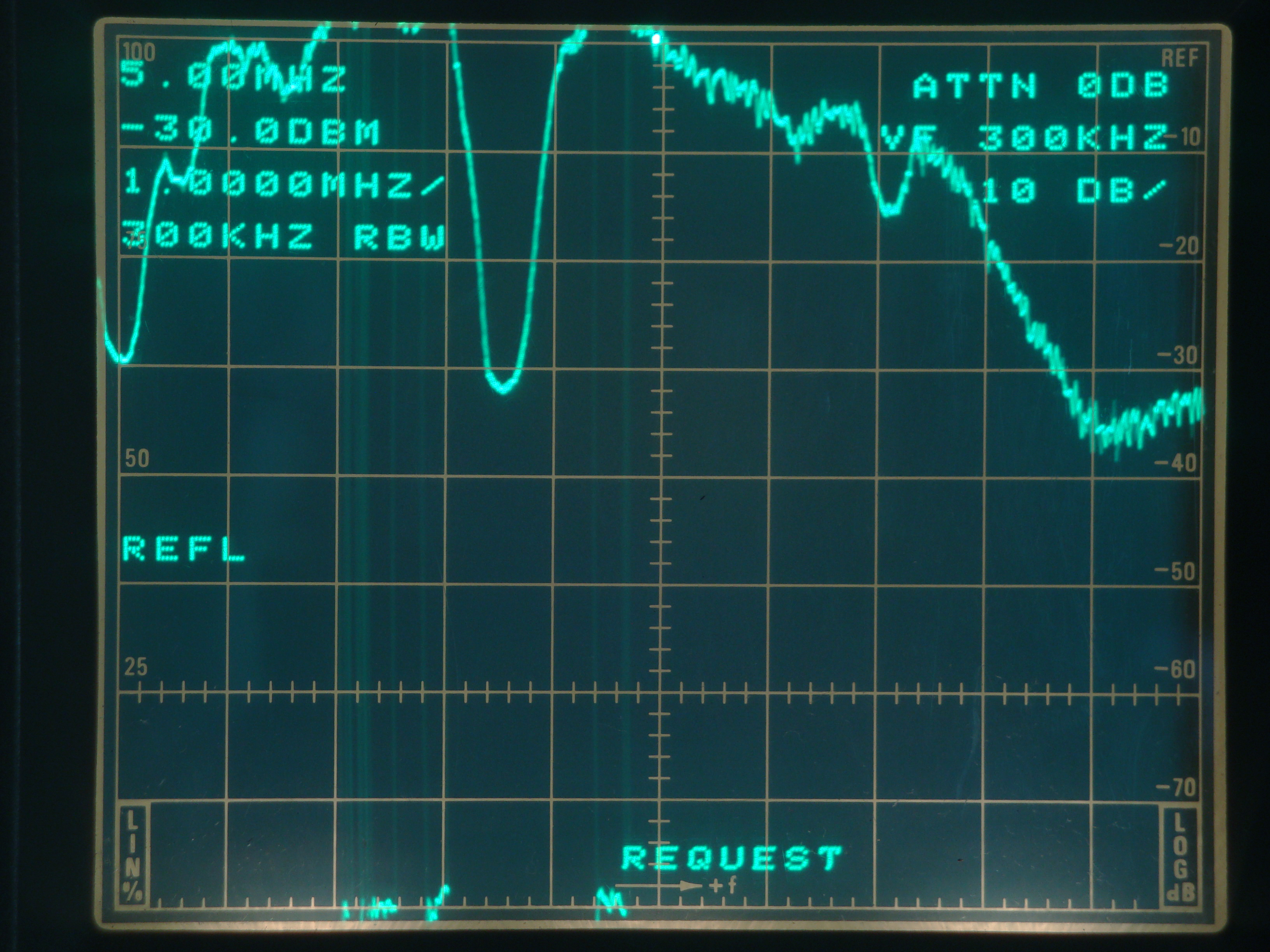
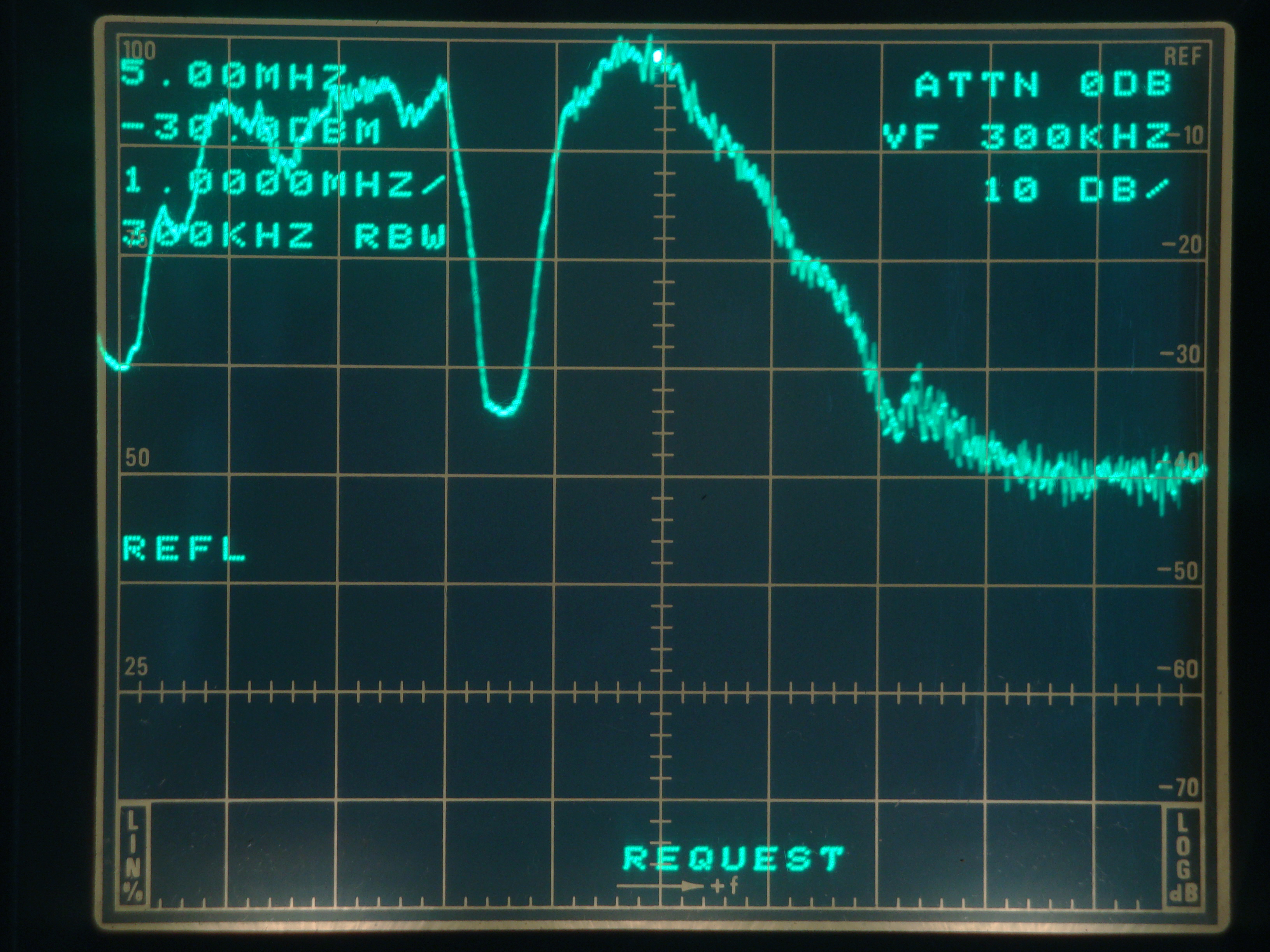
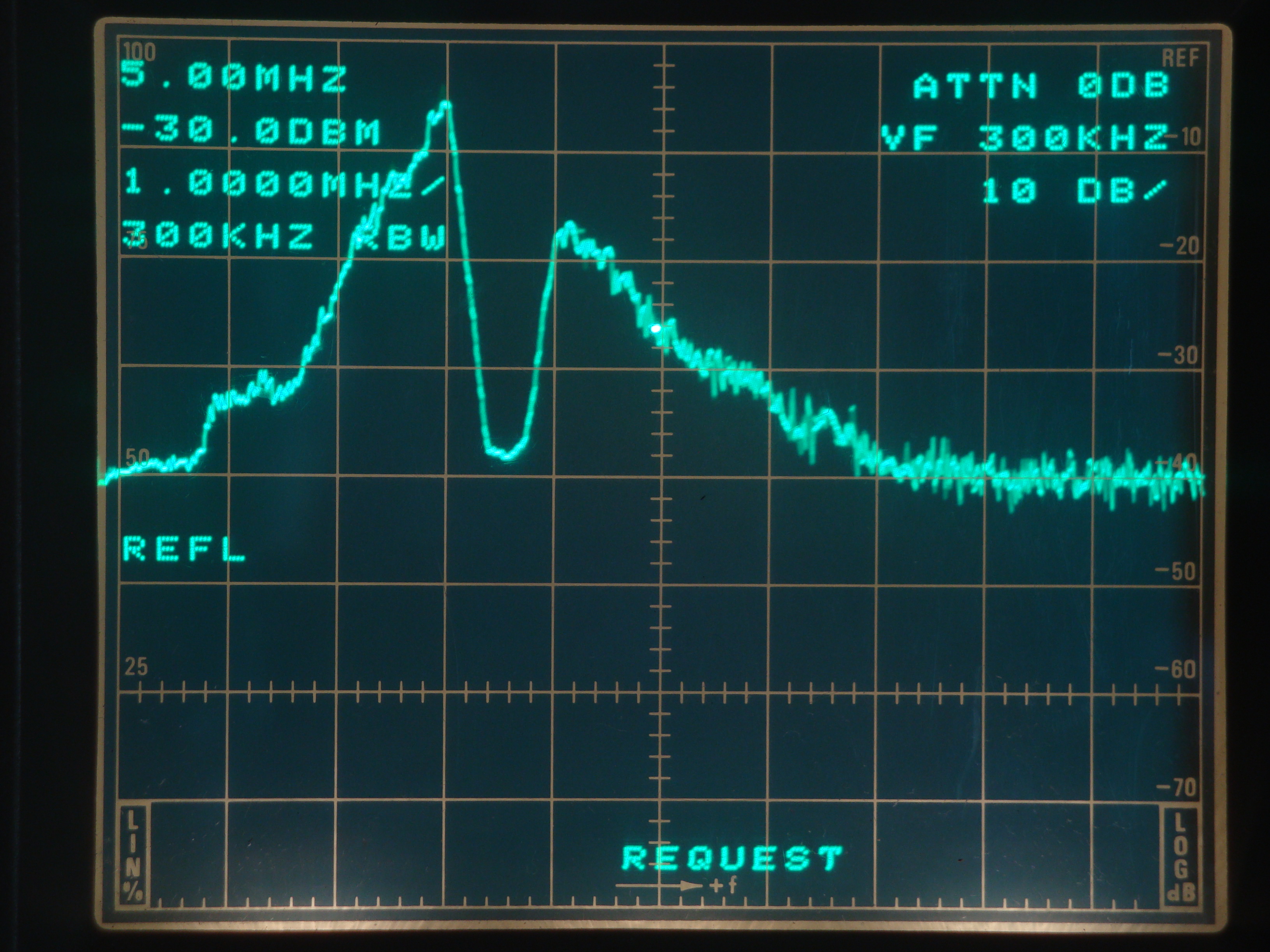
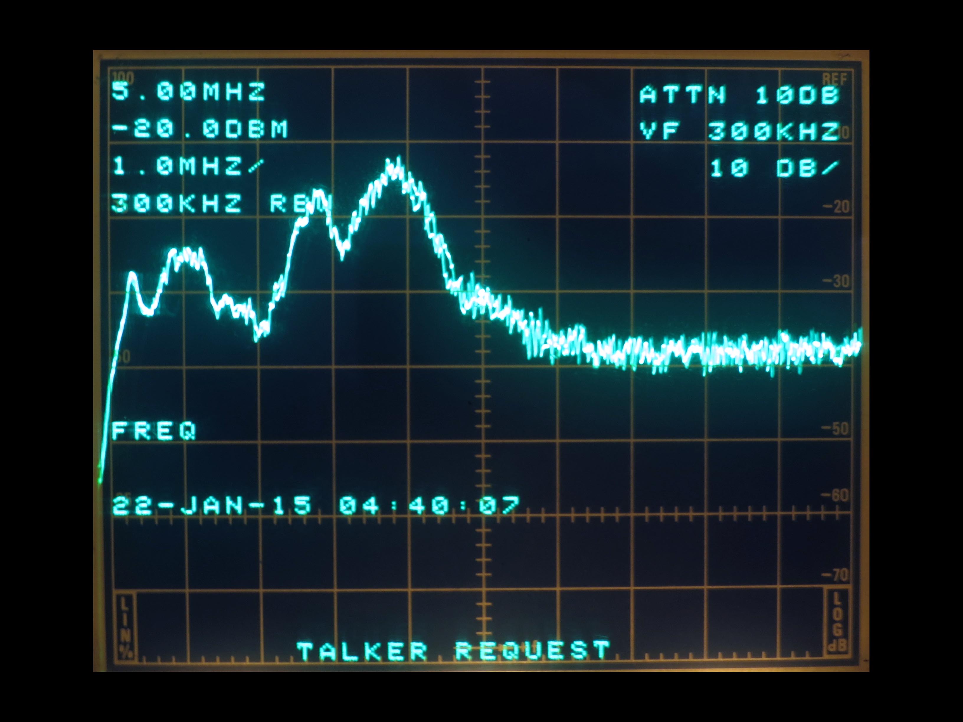
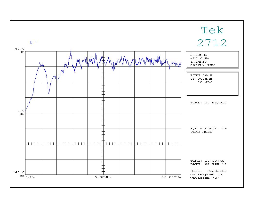
3d) PAE-Kx33 switching supply spectrum, KX3 in transmit (10 KHz-10 MHz)
Image 3a shows the residual ripple of a PAE-Kx33 switching supply with the KX3 in receive drawing 0.2 A, ~4mV p-p at ~27 KHz. Note the lack of any sharp switching transients. Switching device recovery is well damped. The ripple peak-to-peak amplitude is the lowest of all switching supplies tested. The ripple waveform is closest to a sine wave with a peak-to-peak to RMS ratio of ~3.6:1, a sine wave is 2.8:1. Image 3b is the Kx33’s response to a 2 A to 0.2 A current step and back, showing very low overshoot/undershoot and low transverse RF at either current level. Image 3c is the PAE-Kx33 switching supply spectrum analysis with the KX3 in receive drawing 0.2 A, RF output is lower than -80 dBm. Comparing it against that of the battery shows one difference: the small broad rise from 1-4 MHz of ~6-12 dB relative to the battery, and a few spurs which were not audible in the KX3. Listening to 80 M through 6 M no increase in noise was heard relative to powering with the battery. In general the output spectrum is extremely clean, and 20 dB lower than the next best switching power supply tested. The transmit spectrum of 3d shows the output impedance of the PAE-Kx33 to be extremely low from DC through 5 MHz, so the 3.510 level superimposed on the DC line by the KX3 is almost identical to the performance of the battery or linear supply. The average supply noise level remained relatively constant compared to its spectrum at 0.2 A. This supply will be a good neighbor in a multi-op environment.
MeanWell GSM60A15-P1J Switching Power Supply
DC Voltage no load: 15.0 V
DC Voltage receive: 14.8 V@0.2 A
DC Voltage transmit: 14.6 V@2.5 A
AC line to DC output capacitance: ~500 pF
Maximum ripple amplitude: 80 mVp-p
Ripple+noise RMS voltage (10 MHz BW): 2.7 mV
4a) MeanWell switching supply noise, KX3 in receive 20 mV/div, ~80 mV of ripple.
4b) Meanwell switcher current step from 2 A to 0.2 A, ~55 mV of overshoot and a ~20 mS of ringing.
4c) MeanWell switching supply spectrum, KX3 in receive (10 KHz-10 MHz)
4d) MeanWell switching supply spectrum, KX3 in transmit 10 KHz-10 MHz)
Image 4a shows the residual ripple of the Meanwell switching supply with the KX3 in receive drawing 0.2 A, at ~80mV p-p at ~27 KHz. The current step waveform in image 4b shows poor transient response and ringing as well as ~55 mV of overshoot. Referring to the spectrum analysis in image 4c, with the KX3 in receive the average supply noise level is 40 dB higher than the battery supply from 1 to 3.5 MHz which over-ranges the display and re-appears at the bottom. Listening to the KX3 while it was powered by this supply showed a marked increase in a cyclically changing scratchy noise floor on 160 M and 80 M. Looking at the transmit spectrum in 4d @10 W with the transmit frequency at 3.510 MHz, the average supply noise level increased another 10 dB relative to the its performance at 0.2 A.
Ktec KSAS065 Switching Power Supply
DC Voltage no load: 14.2V
DC Voltage receive: 14.0V@0.2A
DC Voltage transmit: 13.6@2.5A
AC line to DC output capacitance: ~350pF
Maximum ripple amplitude: 30mVp-p
Ripple+noise RMS voltage (10MHz BW): 3mV

5a) Ktec switching supply noise, KX3 in receive 10mV/div., ~30mV of ripple.
5b) Ktec switcher current step from 2A to 0.2A, ~44mV of overshoot.
5c) Ktec switching supply spectrum, KX3 in receive (10KHz-10MHz)
5d) Ktec switching supply spectrum, KX3 in transmit (10KHz-10MHz)
Image 5a is the Ktec switching power supply noise at the DC power jack, KX3 in receive drawing 0.2A. The fundamental ripple was ~30mVp-p at ~31KHz. It is hard to see the sharp leading edge spikes in the waveform which consititutes 1/3 of the amplitude. 5B shows the current step response from 2A to 0.2A, well controlled with 44mV of overshoot and no visible ringing. In image 5C, the power supply spectrum analysis with the KX3 in receive drawing 0.2A, we see this supply outputs between 30dB and 40dB of energy between 1 and 5 MHz relative to the battery, slowly decreasing as the frequency rises. Listening to the KX3 there were numerous single-frequency spurs on 160, 80, and 40M which changed frequency as the power draw varied. The Ktec transmit spectrum analysis in image 5d is the KX3 in transmit @10W drawing 2.5A. The average supply noise level remained relatively constant compared to the Ktec at 0.2A.
MFJ 4103 Switching Power Supply
DC Voltage no load: 14.2V
DC Voltage receive: 14.1V@0.2A
DC Voltage transmit: 13.8@2.5A
AC line to DC output capacitance: 1000pF
Maximum ripple amplitude: 15mVp-p
Ripple+noise RMS voltage (10MHz BW): 1.9mV
6a) MFJ switching supply noise, KX3 in receive 5mV/div, ~30mV p-p.
6b) MFJ switcher current step from 2A to 0.2A, ~94mV of overshoot.
6c) MFJ switching supply spectrum, KX3 in receive (10KHz-10MHz)
6d) MFJ switching supply spectrum, KX3 in transmit (10KHz-10MHz)
Image 6a is an MFJ switching supply, KX3 in receive drawing 0.2A, and the fundamental ripple was ~ 30mVp-p of 2.6MHz modulated at 100KHz. The MFJ had the highest switching frequency of all the switching power supplies tested. Although higher frequencies can mean a smaller, lighter supply, the MFJ was the largest supply tested, and this high a switching frequency certainly poses a challenge to the design of the output filter. 6B shows the current step response from 2A to 0.2A, with 94mV of overshoot, the leading edge which is hard to see, but no visible ringing. Image 6c is the MFJ switching power supply spectrum analysis with the KX3 in receive drawing 0.2A. Compared to the battery the MFJ supply had a broad peak of energy centered at 3MHz which reached 36dB relative to the battery at its peak. The MFJ did not have any audible spurs, however an increase in background noise was observed on 80M. With the KX3 in transmit @10W drawing 2.5A, image 6d shows the average supply noise level remained relatively constant compared to 0.2A.
Powerwerx SS-30DV Switching Power Supply
DC Voltage no load: 14.19V
DC Voltage receive: 14.17V@0.2A
DC Voltage transmit: 14.0@2.5A
AC line to DC output capacitance: 11,200pF
Maximum ripple amplitude: 18mVp-p
Ripple+noise RMS voltage (10MHz BW): 0.35mV
7a) Powerwerx SS-30DV switching supply noise, KX3 in receive 5mV/div, ~18mV p-p.
7b) Powerwerx switcher current step from 2A to 0.2A, ~34mV of overshoot (spike hard to see).
7c) Powerwerx switching supply spectrum, KX3 in receive (10KHz-10MHz)
7d) Powerwerx switching supply spectrum, KX3 in transmit (10KHz-10MHz)
Image 7a is a Powerwerx SS-30DV switching supply, KX3 in receive drawing 0.2A, and the fundamental ripple was ~ 18mVp-p frequency dithered between 25KHz and 30KHz. The ripple waveform was very spiky and hard to capture, but it’s waveshape contributed to the increase in RF output. The Powerwerx has a good filter and was designed for 30A output so there was very little ripple at the low currents the KX3 demands. Image 7b shows the current step response from 2A to 0.2A, with 34mV of overshoot, the leading edge which is hard to see, but no visible ringing. Image 7c is the Powewrwerx switching power supply spectrum analysis with the KX3 in receive drawing 0.2A. Compared to the battery the Powerwerx supply had a broad peak of energy between 2 and 5MHz which reached 25dB relative to the battery at its peak. The Powerwerx did not have any audible spurs, and no difference to background noise was heard. With the KX3 in transmit @10W drawing 2.5A, image 7d shows us that the impedance of the Powerwerx supply is low with a moderate increase of 10dB at 4MHz. The high input to output capacitance is a negative for use with antenna systems which cause common-mode currents to flow, as it will encourage coupling to the AC line which can cause RFI.
We also tested a couple of very inexpensive supplies, but due to their poor performance did not perform a complete suite of tests on them:
QTY PB2007 Switching Power Supply
DC Voltage no load: 15.1V
DC Voltage receive: 14.1V@0.2A
DC Voltage transmit: 13.2@2.5A
AC line to DC output capacitance: n/a
Maximum ripple amplitude: 1.3Vp-p
Ripple+noise RMS voltage (10MHz BW): n/a
QTY PB2007 .2-2A ~1V overshoot
ZW 14VA344 Switching Power Supply
DC Voltage no load: 15.0V
DC Voltage receive: 14.8V@0.2A
DC Voltage transmit: 14.4@2.5A
AC line to DC output capacitance: n/a
Maximum ripple amplitude: 1.6Vp-p
Ripple+noise RMS voltage (10MHz BW): n/a
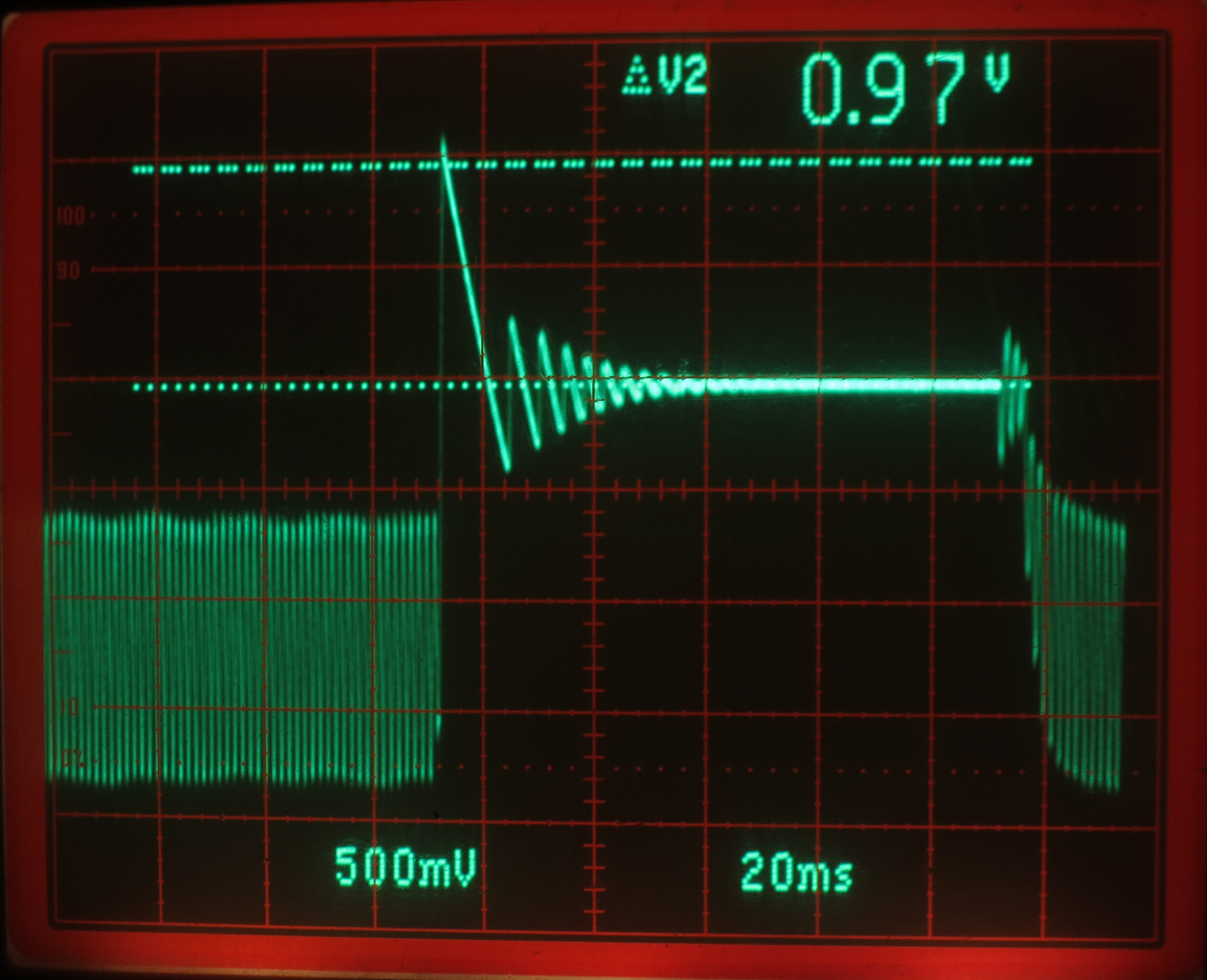
ZW14VA344 .2-2A ~2V overshoot
1) AC Power Supplies and RFI
When powering a 12VDC receiver from an AC line power source you may find the receive noise floor becomes contaminated with noise of various sorts which are not present when powered by a battery and isolated from the AC power system. It is tempting to believe that all of the additional noise originates from within the power supply, but this is often not the case. It is also a common misconception that all linear power supplies powered from the AC mains are as quiet as batteries, and that all switching power supplies are noisy. The truth is more complicated and is due to the multiple routes by which RF Interference (RFI) can be induced into a receiver.
The main routes for RFI are:
1) Transverse-mode conduction of RF ripple superimposed on the DC power supply output can introduce RFI into the equipment being powered. It is critical for the designer of a supply to resolve this source of noise inside the supply as it can cause radiated RFI if allowed to propagate on the DC power cord. We specifically designed the Kx33 to have extremely low RF ripple on the DC output.
2) Common-mode coupling of the antenna system to the AC power line through a power supply can introduce several types of RFI to sensitive receive systems. It is common-mode, since the potential exists between the AC input and DC output, not between either of the AC input or DC output conductors. The magnitude of this type of RFI depends on two main factors:
a) The impedance of the AC input to DC output of the power supply at the frequency of interest. All AC line powered supplies have a combination of inductive and capacitive coupling between the AC line and the DC output. This represents a path for RF energy to take if a difference in potential exists between the two. Measurements taken by PAE show linear and switching supplies to offer mainly capacitive coupling, with ~1000pF being average. At <100pF the Kx33 minimizes this coupling and the magnitude of this common-mode RFI.
b) The magnitude of antenna system voltage on the chassis of the rig. Well-implemented antenna systems with little imbalance and small common-mode feedline currents are less likely to cause this form of RFI. When operating with a high-impedance antenna like many end-fed long-wires, or while operating with an indoor antenna, the use of any line-operated supply can potentially induce antenna counterpoise currents to be coupled to the AC power system through the power supply. When using a linear supply the instantaneous input to output impedance will be modulated at the AC line frequency, leading to the hum commonly heard in older single-conversion receivers. Users of the Heathkit HW-7 will remember this phenomenon. Since the common-mode coupling was modulated at line frequency and harmonics, choking the noise was almost impossible due to the magnitude of inductance required. In the case of a switching supply the coupling can be modulated by the dynamic impedance of the switching action and can cause RFI. Inserting a common-mode choke in the antenna feedline will reduce or eliminate the feedline current flow. An excellent reference on this subject can be found on K9YC’s site:
http://audiosystemsgroup.com/RFI-Ham.pdf
We also offer the #33-410 Fair-Rite Ferrite Clamp-On core at our cost to help remediate this common-mode coupling:
https://proaudioeng.com/accessories/![]()
Passing the DC power cable 4 to 6 turns through this core will effectively increase the common-mode impedance of the DC power cable by >3000 ohms@10MHz, effectively minimizing this source of RFI. We have had a couple of customers inquire as to why we did not integrate this ferrite into the design of the Kx33 itself. The answer is size, weight and cost, the ferrite is over 1/2 the weight, ~1/2 the size of the KX33, and would have greatly increased the cost. For 99% of all uses, the RFI performance of the Kx33 itself will be sufficient, and those users will enjoy a much smaller, lighter power supply at lower cost.
3) Radiated RFI from many sources can be picked up by the antenna system and appears as a signal in the receiver. In a well-designed supply like the PAE-Kx33, the external fields from the high-current PCB loop between the switching devices and transformer, as well as the fields of the transformer itself are extremely small. In order to minimize the pickup of any radiated RFI we recommend placing the supply the full length of the DC supply cord away from the rig.
Out of ~1000 customers less than 1% have experienced any additional RFI caused by proper use of the Kx33. Of those that have, addition of the ferrite core has remediated the noise. We are sure you will be happy with the Kx33 or we will refund both your purchase and shipping costs, so there is no risk other than a small amount of your time evaluating it.
2) Using Lithium Battery Chargers as Power Supplies
Recently Elecraft released it’s KX2 HF Transceiver with a 3-cell Li battery pack. We have received many emails asking if the Tenergy charger Elecraft sells can also be used as a power supply for the rig. There are several problems with this:
- The Tenergy charger has a large amount of RFI, as it was not intended to be used to power an HF rig. We tested three power sources with the identical setup: An 80AH PbA car battery, our own Kx33 Low-RFI 14 V 4A supply, and the Tenergy F111-020-D. All three are normalized to the noise floor on the DC Input jack (0.0dB on the Y axis) when powered by the battery, the noise level at the 0.0dB line is actually -60dBm. The spectrum analyses of the three are revealing:

80AH PbA Battery, 0.2A
PAE-Kx33 14V 4A Low-RFI Supply
Tenergy F-111-020-D
As is obvious, little attempt was made during the design of the Tenergy Charger to control conducted RFI, with broadband RF output at over 30dB above that of the Kx33 or battery. Radiated RFI is also much worse for this supply than for the Kx33, but keep in mind it was not designed to power an HF rig..
2. The output voltage of the Tenergy charger is not steady with respect to current, but this is proper for the design of a charger. A battery charger monitors the voltage and current of the battery and will reduce the voltage in response to a battery which is approaching full charge. In a modern Lithium charger, if a full charge is not achieved in 2 hours the charger will shut down, as it indicates a faulty cell in the battery, and lithium batteries can be thermally unstable if one of the cells is defective.
3. Load dump performance of the Tenergy charger is very poor. A critical characteristic of a properly designed supply is it’s ability to control output voltage as a load is removed. The Tenergy shows over 1V spike when a 2A load is removed, which is extremely poor, but then, it was not designed to be a power supply, so we cannot blame the design. In one test with a KX2 at 10W into an actual antenna with high SWR the unit was drawing a bit over 2A, and when we entered transmit, the supply shut down, and took the KX2 down with it. Fortunately the KX2 powered up correctly after we power-cycled the supply but this sort of unscheduled power interruption can wreak havoc with settings in a digital rig.
In addition, use of a supply like the Kx33 with 13.8 to 14V will allow full power with excellent voltage headroom. This will allow peak voltages in the transmit waveform to pass with potentially lower IMD.
3) Fusing the Kx33.
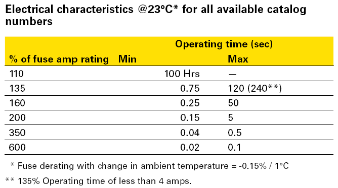
The Kx33 has several protection circuits built in, including over-current. Between 5.1 and 5.3 A it will shut down totally and not attempt to restart until the overload is removed. It does this MUCH more quickly than a fuse. As you can see from the Eaton ATC type characteristic chart below, if you have a 4 A ATC fuse in line with your QRP rig, it will take 120 seconds to blow at 5.4 A, whereas depending on how low the resistance of the short circuit is, the Kx33 will shut down in <50 mS after the output filter capacitor discharges.
Of course if the supply is outputting 14 V and the a QRP rig is drawing that much current there is something shorted in it already. In the case of an external supply supplying too much voltage, a fuse will not protect the rig until something internal shorts due to the over voltage, then the fuse protects the wiring and power supply. Most modern rigs have both reverse and over-voltage protection built in, as does the IC-705 and KX2/3 (strangely, not the Xiegu G90). The Kx33 has internal over-voltage protection to protect the rig in the first place.
I cannot think of a good reason to put a fuse between a Kx33 and a rig…between a battery or high-power supply and rig, of course! In these cases the current is unlimited, and if a rig develops an internal short, you don’t want a wiring fire or exploding battery in addition to a dead rig!