

The Dual EAS7 Yagi is a dual-band EAS Yagi antenna specifically designed to provide an all-in-one solution for EAS monitoring of both FM and NOAA Weather Radio (WR) stations.
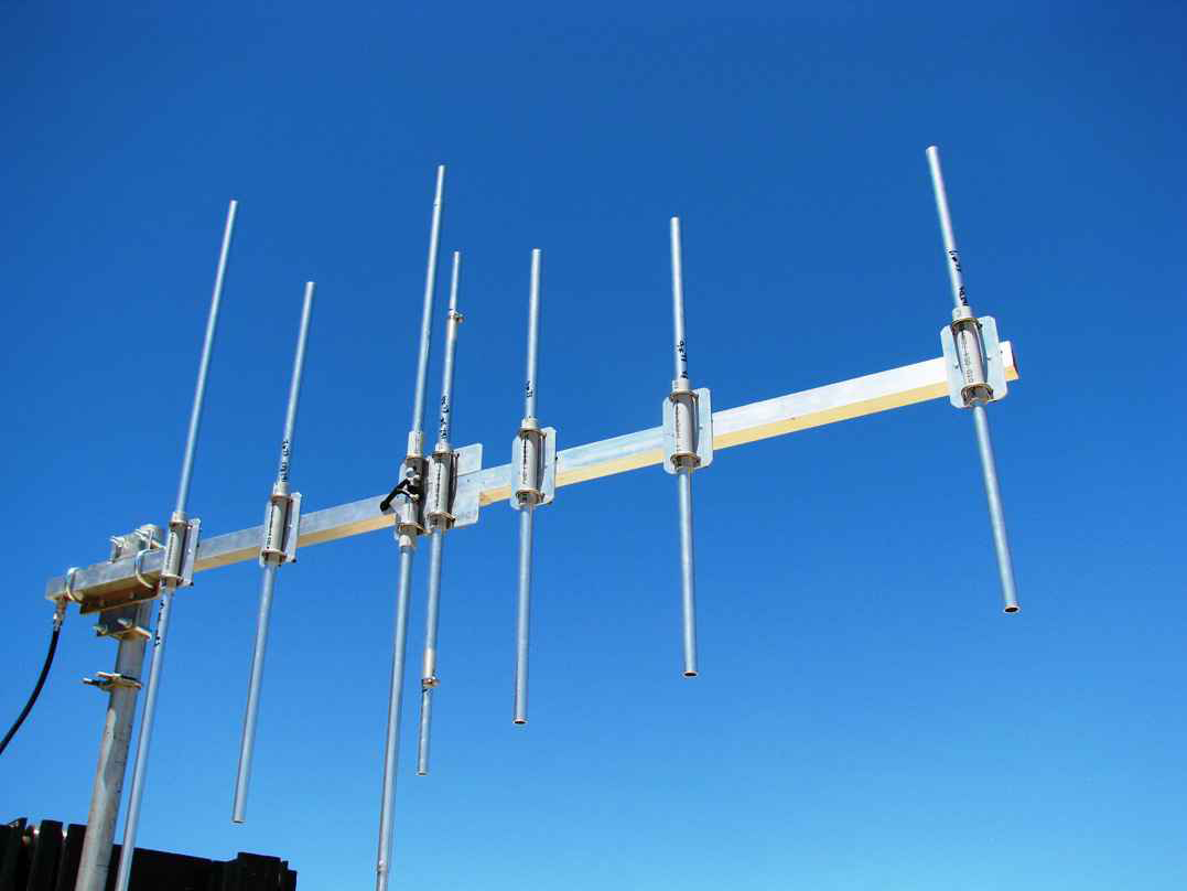
The 88-108 MHz FM section of the antenna is a 2 element Yagi design using a driver element and a parasitic reflector. Since most FM stations being monitored have a relatively high ERP of 10KW to 100 KW, the two element design allows for a wide azimuthal range of reception with adequate gain.
The 162 MHz NOAA WR section is a 5-element Yagi with the reflector element behind the FM driver and the remaining elements in front. The high gain afforded by this 5 element Yagi is beneficial since most NOAA WR stations transmit with a relatively low 1 KW signal and can be quite weak in some areas which are terrain shielded or remote. The NOAA WR Yagi is fed using a parasitically-excited driver element in an “open sleeve” configuration.
Both Yagis present a nominal 50-ohm impedance at the common feed point, which is the FM driver element. The coax feed line is physically connected only to the FM driver element, which is split at the center.
Construction
The DualEAS7 is intended as a receiving antenna; however, it can also be used for transmitting, with a power handling on the order of 600-1000 watts CW. The internal balun uses LMR240-UF with five ferrite beads and the coax connection is a female N-type bulkhead secured to the boom.
The default mounting is specified for a 2” pipe mast, although other sizes can be specified at the time of order. The square boom has a wall thickness of 0.125” and the element mounting plates are both riveted and welded to the boom for a literal one-piece boom of maximum strength.
The elements are mounted to rectangular mounting plates using a pair of stainless U-bolts clamping over the aluminum elements sleeved with slotted PVC. The PVC is electrically an insulator; however, the main purpose for the PVC is to prevent the U-bolts from compressing/creasing the elements due to over-tightening the U-bolts. Yagis constructed in this manner using PVC element insulators have been field tested for over 30 years in many environments from desert to the Antarctic.
The boom is open on both ends, so any rain will drain out either end. The ends can be capped if desired. If they are left open, the center of the N-connector inside the boom can be covered with appropriate silicone (non-contaminating) for further weather proofing.
The Dual EAS7 has been designed to survive 125 MPH winds or 90 MPH winds with 1/2″ of icing.
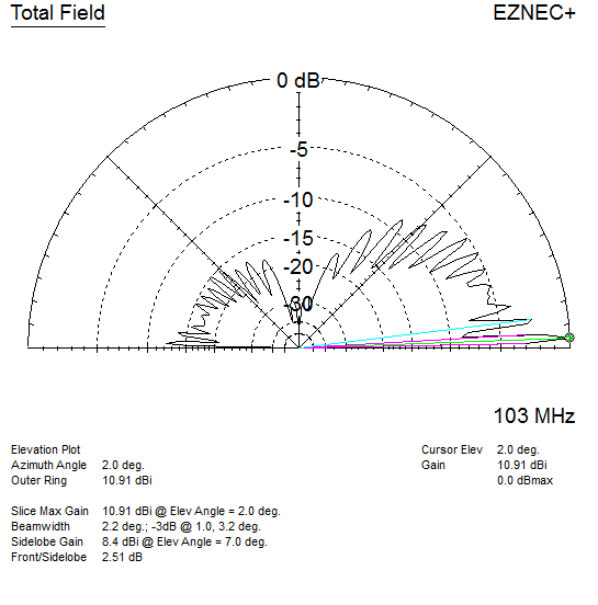
FM Performance
The elevation plot below is for the 2 element FM portion of the DualEAS7. The pattern is calculated at an installed height of 25′ over flat ground. The gain is shown at a height of 2° and mid-band (103MHz) is 10.91dBi The rear pattern (F/B) is down slightly more than 12dB.
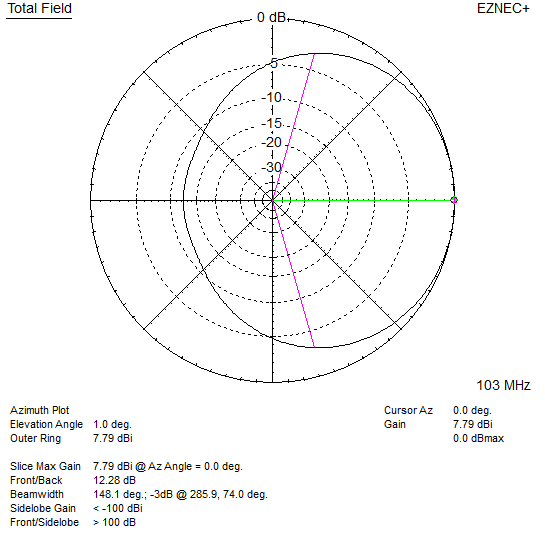
The plot below is the azimuth plot for the FM portion of the DualEAS7 at 103MHz. This is also modeled at a height of 25′ above ground and at a 2° angle. This view is looking down on the antenna from above. It shows the width and gain of the antenna pattern in all directions. As can be seen, this is a nice, broad pattern that can effectively receive FM signals from any direction that is +/- 90° from the aimed direction. For FM signals off to the back, they will be down about 12dB, which most likely will be still reasonably strong given the relatively high ERP of most FM stations.
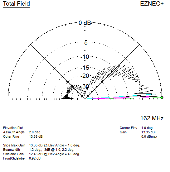
NOAA WR Performance
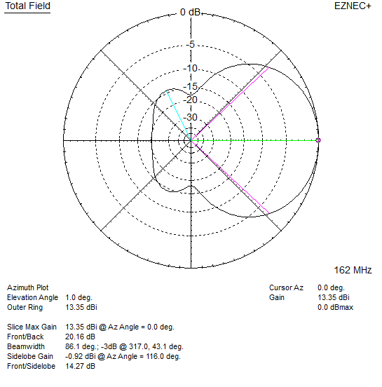
The elevation plot below is for the 5 element NOAA WR portion of the Dual EAS7. The pattern is calculated at an installed height of 25′ over flat ground. The gain is shown at a height of 1° and at 162 MHz is 13.35dBi. The rear pattern (F/B) is down slightly more than 20dB.
The plot below is the azimuth plot for the NOAA WR portion of the Dual EAS7 at 162 MHz. This is also modeled at a height of 25′ ave ground and at a 2° angle. This view is looking down on the antenna from above. It shows the width and gain of the antenna pattern in all directions. As can be seen, this is a much narrower pattern than the FM portion; consequently, it is imperative that the antenna be correctly aimed to receive the NOAA WR signal.
Ordering
Contact Pro Audio Engineering via email to: info@proaudioeng.com to obtain a quote.