Kx32 Heatsink for the Elecraft™ KX3 (click for new window)
P/N: PAE-Kx32 Price: $89.90
Shipping Status: Immediate, In Stock
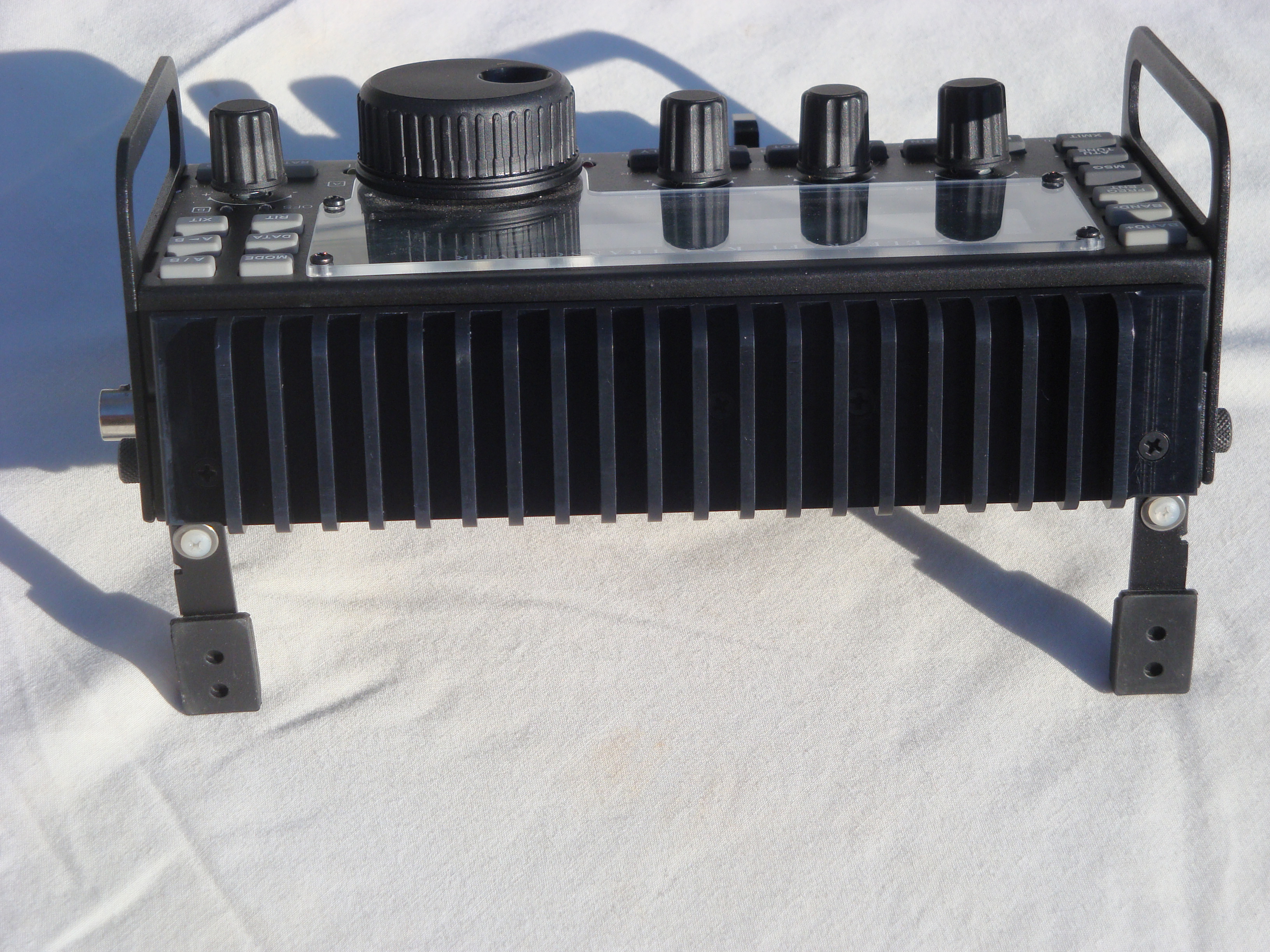
With the advent of increased 15W power output for the Elecraft™ KX3, more owners than ever are finding it difficult to keep their rigs cool. We are proud to announce the release of the ultimate heatsink for the Elecraft™ KX3: The Pro Audio Engineering Kx32! Like its Kx31 brother, it is designed using thermal modeling and offers the maximum cooling by natural convection. Only slightly larger than the Kx31, the Kx32’s performance exceeds the Kx31 by 25% or more depending on band. The Kx32 is a billet-aluminum piece black-anodized to match and compliment the appearance of the rig. It is designed for serious digital mode operators and will allow for greatly extended transmit time in any digital mode or band at full output. The Kx32 incorporates several features not found on competing heatsinks:
- Designed using thermal modeling software for best performance.
- Ratio of base mass to fin area optimized for the duty cycle of digital modes.
- Rounded cross-section for no-snag use in fabric cases, and no sharp corners to cut or damage adjacent objects.
- When mounted on Elecraft™ KX3 along with GemsProducts™ SideKX plates and cover, the combo will fit in a standard Rose’s KX3 case.
- Custom-color black anodized instead of powder-coated for superior thermal performance.
- Radiusing compliments the design of the Elecraft™ KX3 and the GemsProducts™ SideKX.
- Its design interlocks with and greatly enhances the impact resistance of the SideKX Cover.
- Custom fin spacing matches KX3 screw placement for a clean appearance, unlike others it does not look like a stock heatsink profile modified to fit.
- Optimum compromise for most all operators between stock appearance and enhanced transmit time.
- The Kx32 is supplied with correct longer replacement black-oxide stainless steel screws and a packet of heat-transfer grease.
- The Kx32 offers the maximum dissipation allowed by the footprint of the KX3’s top surface.
- In addition the Kx32 offers the highest performance in the minimal volume as proven by multiple tests.
- The Kx32 offers the best performance value of any aftermarket KX3 heatsink, delivering more cooling than all others.
- Each heatsink is visually checked after machining, and again after anodizing to make sure there are no defects before being shipped to you.
Size: 7.125″ x 1.75″ x 0.750″
Weight: 7.2 oz., 204 g.
Color: Custom dye batch black to match the Elecraft™ KX3
Thermal Resistance: <2.15°C/W
Surface Area: 48in²
Warranty: The Kx32 is warrantied against all manufacturing defects. Read all Warranty details here.
Key-down Transmit Time Improvement:
160M-430%, 80M-350%, 40M-350%, 20M-300%, 15M-300%, 10M-430%, 6M-550%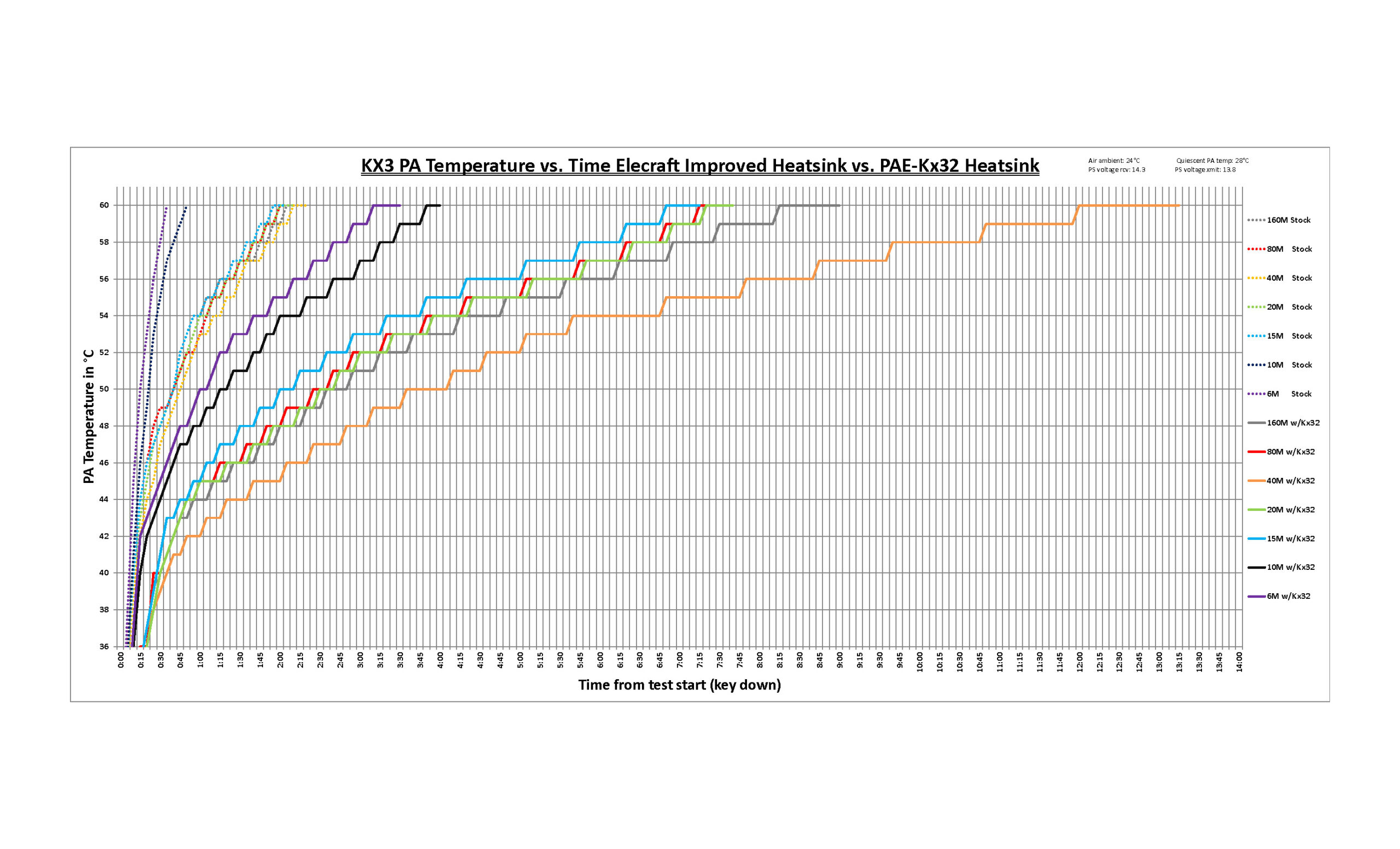
In order to validate the design, we ran a complete set of stock and modified performance tests. The test was conducted with a air tunnel around the KX3 to restrict the air movement to the convective flow powered by the heatsink itself. This removes room air movement as a variable, since almost undetectable amounts of movement can greatly increase the heat removed from a heatsink.
NOTE! (Please be wary of other ‘s claims that the same size or smaller heatsink can dissipate more heat than can the PAE-Kx32. Their claims are often the result of poor experimental design or outright guessing. We know of no other test done with a shield to eliminate external air movement, which can increase the cooling by 100% or more but is an uncontrolled variable. In most normal environments the PAE-Kx32 will allow much more transmit time than our own data supports.)
Also, the object of the tests was to validate the performance of the Kx32 heatsink, not evaluate the thermal conductivity of powder-coating, the thickness of which is largely an uncontrolled variable. To test the heat flow through the coating would mean the results would not necessarily be reproducible. To reduce this variable the case was prepped by removing the powder-coating from a 1″ x 2″ area around the PA transistor mounting holes, and heatsink compound was used between the transistors and case, as well as between the case and heatsink. We ran the KX3 RF output into a Bird Termaline 50Ω load, and measured RF power output with a Bird 43 with a 25H element. The DC power was provided by a Xantrex HPD 30-10 supply and was monitored using an HP 3468B DVM. 3 trials were averaged on each band pre and post-heatsink mod, and the summary data is posted below:
160M-430%, 80M-350%, 40M-350%, 20M-300%, 15M-300%, 10M-430%, 6M-550%
From the data above you can see that the improvement in key-down time is as much as 400-500% or more, depending on band. Our goals were to be able to run 12-15W in digital modes for extended periods on all bands without power fold-back, and to do as little harm as possible to the excellent appearance of the KX3. This heatsink achieves both goals without any fans and without being excessively large.

Kx31 profile compliments SideKX cover and KX3 (click for new window)
We spent quite a bit of time modelling the thermal situation with the KX3. In the stock configuration the entire case back is an important part of the thermal equation, but it is not with an external heatsink. At 0.062″ thickness the thermal impedance of the sheet aluminum case back is relatively high compared to a dedicated heatsink on top. An important design factor for heatsinks cooled by natural convection is the surface area upon which the heat can transfer to air by contact. The fin-height to space ratio should not exceed ~2:1 or the velocity of air will be slowed by viscous shear friction. Radiative efficiency is important as well, but in a parallel-fin heatsink, much of the heat radiated by the fins is merely absorbed or reflected back by adjacent fins.
Kx31 custom fin pattern perfectly matches KX3 screw locations. (click for new window)
The models show, and our testing with three different designs has borne out that over the footprint of the KX3 top utilizing normal convection, and regardless of fin design, the maximum amount of heat which can be consistently removed at room temperature is in the 6 watt range without hitting the 60°C PA temp limit. In order to bypass this limitation we decided to extend the Kx32’s design an additional 1/4″ to the back of the rig to achieve additional fin area. This plus an additional 1/8″ of fin height gives the Kx32 ~8w of natural convective dissipation. The Kx32 extends past the case but does not interfere with the rig laying flat. Beware claims by others that their designs can dissipate more than this. They have obviously not tested for pure natural convection. Consider the KX3 PA rejects 10-15 watts of heat or more (band dependent) while outputting 10W, and you will see that infinite key-down is not possible without a fan. With the advent of the 15W power limit on some bands the amount of heat rejected to the heatsink is even higher, potentially in the 15-20W range. Utilizing natural convection power-reduction due to hitting the 60° thermal fold-back is inevitable. Elecraft themselves never claimed the unit was 10W with all modes on all bands, so for those of you who have not looked, here is their PA specification:
“10 W PEP, 160-15 m; 8 W PEP, 12-6 m; 2 m (KX3-2M): 2+ W, 144-148 MHz.
Supply voltage of 11 V or higher (on key-down) required for settings above 5 W.
5 W or less recommended for high-duty-cycle modes (FM, AM, DATA). Power will
automatically be reduced if PA temperature or current limits are exceeded.”
( from KX3 Owners Manual Rev C2 (August 13, 2013), pg.52)
In addition, with the release of MCU firmware 3.68 Elecraft now states:
“- Up to 15 W power output (all modes) on 80-20 meters…Note on 15 W output level: This requires a power supply voltage of 12.8 V or higher on key-down as indicated by the KX3 itself (on the VFO B display). All of the usual firmware protections apply, i.e. the KX3 will roll power back to a lower level if necessary to keep current drain and temperature within a safe range, or if supply voltage is too low. 12 W max is the generally recommended level, so 15 W should be used only when really needed…”
( Elecraft announcement 12/28/2015)
The KX3 PA designers hit an excellent compromise for 90% of KX3 owners. Considering the PA is broadbanded and consistently achieves low IM distortion performance the design is nothing short of amazing. However, many owners would like to have the full 12W available on all bands for extended digital mode transmit time, and use the 15W available when desired. As many have found out, the stock PA thermal solution is less than optimum for extended transmit time at 12W, and for common digital mode usage, especially on the 10M and 6M bands where the limitation is worst.
Kx31 interlocks with SideKX Cover (click for new window)
As with the smaller Kx31, if you are a Side-KX cover owner you will enjoy enhanced protection from the cover when you mount the PAE-Kx32 heatsink. It interlocks with, and stiffens the top edge of the cover and gives additional protection from impact without making the cover more difficult to install or remove.
Since originally designing and offering the PAE-Kx31, imitators have come on the market, copying features we pioneered like the SideKX cover reinforcing lip which also allows for more heat dissipating heatsink area. Why buy a heatsink from a company copying the original and best? The PAE-Kx32 incorporates more engineering than the competition, so get the highest-performance of any comparably sized heatsink: the PAE-Kx32.
1) What is the difference in thermal conductivity between the different materials used with heatsinks?
When evaluating a thermal path it is important to not confuse ‘Thermal Resistance’ and ‘Thermal Conductivity.’ As quantified in the table below, one is simply the reciprocal of the other:
Thermal resistance is expressed as the degree Celsius rise per Watt of applied heat over a square meter of the material.
Thermal conductivity is expressed as the amount of heat in Watts which is applied to a square meter of the material to raise it one degree Celsius.
Here is a table listing the thermal characteristics of different materials found in the path of heat flow of an Elecraft KX2/KX3:

From http://www.engineeringtoolbox.com/thermal-conductivity-d_429.html and
www.bergquistcompany.com
One conclusion you can draw from this chart: It is prudent to exclude air from the thermal path wherever possible due to it’s extremely high thermal resistance. Let’s follow the heat as it is generated by the KX3’s PA FETs as it flows through the various surface interfaces to its release into the ambient environment:
- PA FETs to Case Inner Surface: As delivered by the factory the PA FETs are mounted dry to the inside of the KX3 case, so it is advantageous to apply a thin film of thermal transfer paste between the two to bridge the gaps, displace air and increase thermal transfer.
- KX3 Case to Heatsink: The outer surface of the case of the Elecraft KX3 has a textured powder coating. Due to the flexibility of the thin aluminum case, over 95% of the heat will be transferred through a 1″ x 2″ (25 mm x 50 mm) area centered on the two PA FET attachment screws. In this area a thin application of gap filling thermal transfer paste on the powder coating surface is advantageous. It will help to displace the air trapped in the valleys of the textured powder coat as well as bridge the flexed thin aluminum case surface between and around the screws. The transfer can optionally be enhanced further by removing the high thermal resistance powder coating to expose bare aluminum. In contrast to a KX3, a computer CPU and heatsink have their mating surfaces very flat and smooth and very importantly rigid to facilitate thermal transfer, however the KX3s case is many time more rough and flexible, so filling the resulting air pockets and gaps is advantageous.
- Heatsink to Air: From the table above you can see that the thermal conductivity of an Type III (hard coat) anodize is as much as 800 times more than that of polyester powder coating, or 200 times more than a typical acrylic paint base resin. This is the reason why, if a coating is required, anodizing is the surface treatment recognized industry-wide as the best way to finish a heatsink. The other reason PAE employs a Type III hard coat anodize on our heatsinks is to render the heatsinks far more resistant to damage, since a Type III anodized surface has a hardness of 60-70 on the Rockwell C scale.
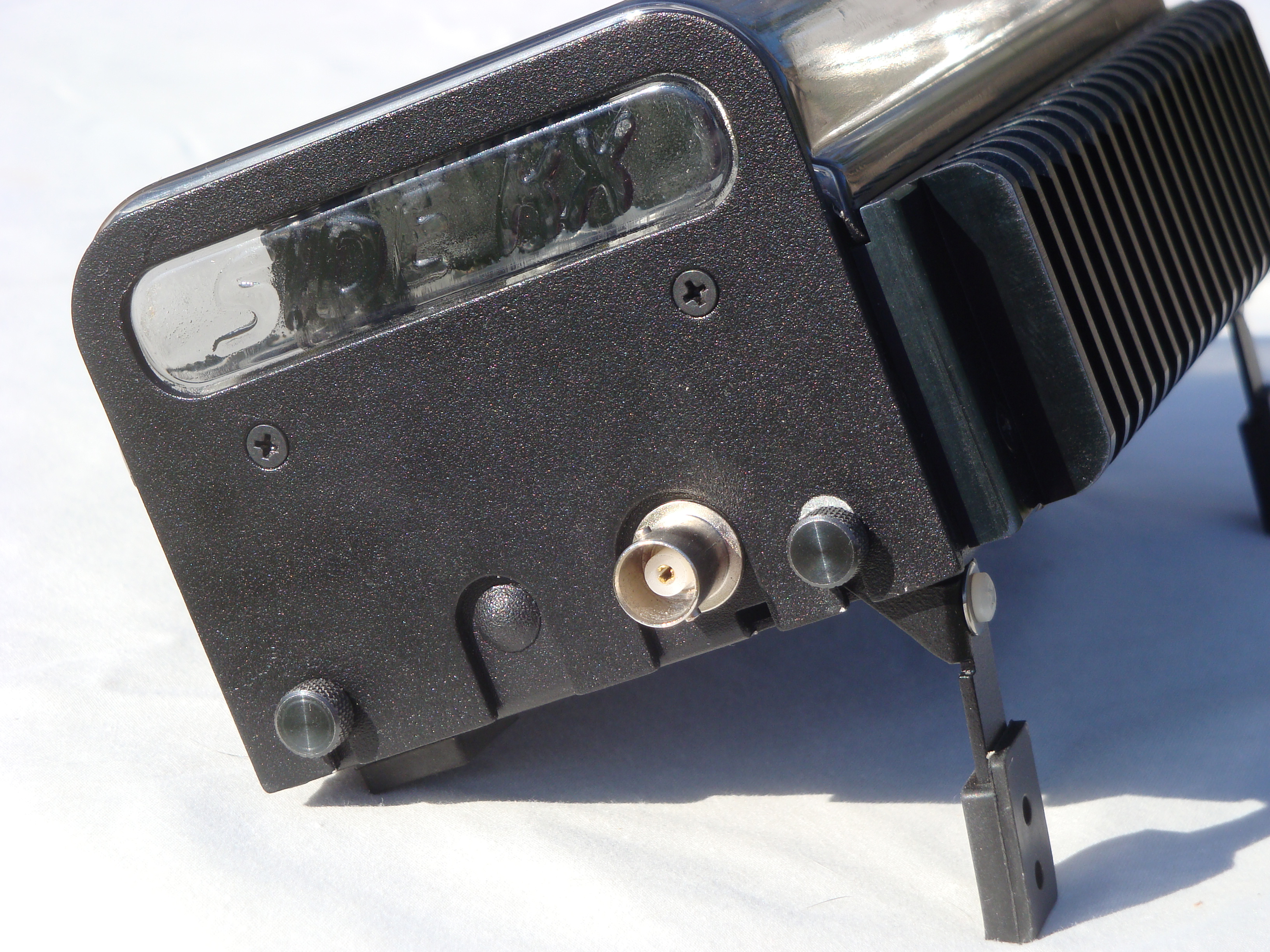
2) I have a new KX3 with the stock Elecraft enhanced heatsink. I’ve removed the screws but it is stuck on very tightly. How do I remove it to install the Kx32
The Elecraft Enhanced heatsink is held on by a piece of thermal transfer film. The adhesive characteristics of this tape rapidly diminish when heated. The good news is that a regular hair dryer can provide enough heat to reduce the adhesion sufficiently to release it. Thermal fold-back for the KX3 is set by Elecraft at 60°C, and a hair dryer outputs air at about 50-60°C (122-140°F). This will release the adhesion with no chance of damaging the powder coating on the KX3. Powder coating softens at around 100°C (212°F), and melts at around 150°C (302°F). We installed one here on a test KX3 and after thermal cycling to 60°C six times then allowing 48 hours for the adhesion to cure at room temperature we indeed found the heatsink to be stuck.
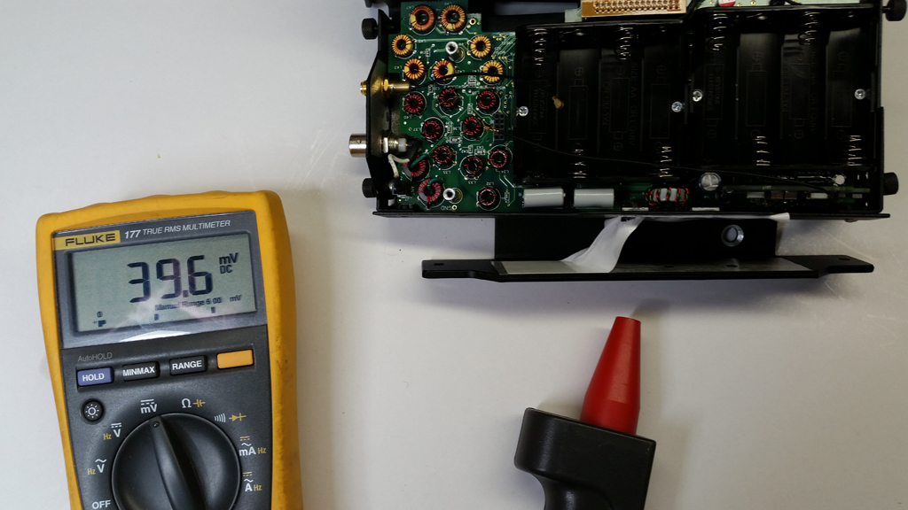
Elecraft Enhanced heatsink removal @ 40°C
Simply heating it with a hair dryer to 40°C and pulling up on the bottom part of the “L” shaped heatsink with steady pressure was enough to allow it to be removed. If you are using a hair dryer, the temperature may rise to 60°C. This poses no potential damage to the KX3 and will make the tape that much easier to release.
There was no damage to the powder coating on the KX3, nor should there have been given the high melting point of powder coating.
Some of the new enhanced heatsinks may be stuck more firmly than ours, and will require persuasion. While heating, A flat-bladed screwdriver wedged between the case and the heatsink on one side will provide the necessary leverage to begin separating the two.
Note in the picture at left the thin white thermal transfer tape still partially hooked to both the KX3 and heatsink.
3) Why don’t you offer a thermal pad for mounting the Kx32, I read they make the KX3 run 3° cooler?
The reality of the statement: “using a thermally conductive pad between the powder-coated case and the heatsink is 3°C cooler” is that using the pad is better than no thermal interface material at all. Both options are inferior to the Option #3 outlined in the PAE-Kx31 manual, or even the Option #2. While an exact analysis would be both lengthy and obfuscating to most people, I will attempt to summarize the situation regarding the KX3 heatsinking options. First we must understand the relative thermal impedance of the materials involved. Thermal impedance is a material’s resistance to conducting heat. The chart below is expressed in in2 °C/ W, or the temperature drop per square inch per watt of applied heat:
Thermal compound<0.1mil: 0.02
Polyester powder coating, 5mil: 1.5
Silicone thermal pads: 0.4
Air: 50
Analyzing the numbers given in the chart, you would correctly conclude that you do not want to be transferring heat through air. This is why the science of thermally interfacing two surfaces is the science of eliminating the air layer between them. If two surfaces were perfectly flat the air would be excluded and no additional interface aids would be required. As it is in reality, the surface textures only allow the peaks of each surface (called asperities) to touch and directly transfer heat. The thermal interface aids fill the voids between the asperities and are designed to be lower thermal impedance than the air they displace. With this in mind:
Option #3:
If you follow the installation option #3 in the PAE-Kx31 manual (removing the powder-coating directly around the PA FETs) , the heat only has to move from the PA FETs through 2in2 of 0.063″ thick aluminum before it is inside the heatsink and being spread throughout the fins for convective removal. Keep in mind that using this method, much of the heat is transferred directly from the FET base to the aluminum case to the aluminum heatsink with very little interface thermal impedance, the thermal compound merely fills voids to enhance heat flow across them. This is why the very best application of the compound is very thin…translucent. You want it thin enough to flow away from the high-pressure areas and let the aluminum surfaces directly touch. The thermal compound is there only to fill the microscopic scratches where there is no direct contact, and the bottom of the PAE-Kx31 is extremely flat (<100uin RMS) to ensure good contact.
Option #2:
If you leave the powder coating on and spread some thermal compound on top of it as described in the PAE-Kx31 manual option #2, the compound will fill the voids, replacing air with thermal compound and enhancing the thermal transfer across the powder coat layer.
Thermal Pad Option:
In thermal interface engineering the thermal pads were developed to address moving heat between surfaces which were non-flat, as well as providing electrical isolation, and they can also lower the cost of assembly compared to thermal compound. They were not developed to have lower thermal impedance than thermal compound.
If you leave the powder coating on and use a thermal pad the heat must first move through powder coating and then through the thermal pads, the best of which are 5-10 times higher thermal impedance than thermal compound. The powder coating thermal impedance itself is 3x higher even than the pad. Regarding the idea that the pad allows the whole back of the heatsink to be in contact with the case: PAE’s recommendation in installation Option #3 is to remove the powder-coating from a 1″ x 2″ area on the KX3 case back directly surrounding the PA FETs. This results in 2in2 of area to directly transfer heat. For heat to move out of this area along the case back, it has a path which is only 0.062″ thick by 3″ long, so the heat moving sideways along the case away from this area must move through less than 0.2in2 of additional heat transfer area. The thermal impedance of this heat path is 10 times that of the 2in2 surface the PA FETs are mounted on, so less than 1/10th of the heat conducted directly THROUGH the case back moves ALONG the case back. This means the case back outside of that 1″ x 2″ area will not be substantially used to transfer heat to the heatsink.
Still, using a thermal pad will outperform dry mounting the heatsink because the pad is compliant and fills the voids in the powder coating textured surface.
Executive Summary:
Method #3 of removing the powder coating and directly mounting the heatsink with added thermal compound is much better than a big thermal pad in series with powder coating. Second best would be to use the heatsink grease directly on the powder coating and then mount the heatsink, which is the method #2 in the manual. Exactly how much worse the pad is than Option #2 or #3 depends on the flatness of the case and the exact pad used. If you just plain don’t want to get thermal compound on your KX3, use a thermal pad, but be warned, over time and pressure they can stick and discolor surfaces as well.
4) Why aren’t more fins better?
On the surface if it, this would seem to make sense, the more fins, the more area for heat to be conducted from the base of the heatsink. So it stands to reason if more fins are better in a given area, carried to it’s extreme a solid block conducts heat from it’s base the best of all, which is true! The problem with a solid block is it has little surface area for the surrounding air to touch and remove that heat, so we accept the need to have fins to increase surface area.
Although we are normalized to moving through it every day without noticing it, air is a viscous substance. The standard unit of viscosity is the centipoise, and water at 68.4°F (20.2°C) has a viscosity of 1.0 centipoise. Air at this temperature has a viscosity of 0.01983 centipoise, or roughly 2% that of water. It sticks to surfaces as well as water does, so air flowing between fins is similar to water flowing through a pipe. The smaller the space it is flowing through, the higher the resistance to flow. This is because the air molecules touching the surface of the heatsink are stationary on it, they are literally attached. They also strongly interact with the air molecules next to them. It takes work to pull the molecules apart, a function called viscous shear. This work is the resistance to air flow. The other main factor determining the optimum amount of fins is fin height. The deeper the channel the air is flowing through, the more difficult it is for the viscous air to move to the base of the fins, and the result is a diminishing advantage to additional height at some point as the air stagnates at the fin’s base.
In a heatsink designed for natural convection (no fan) the force moving the air is merely the difference in density between the air heated by contact with the heatsink fins and the cooler air below it. The heated air rises, pulling cooler air into place behind it. Heatsinks designed for use with fans can employ closer and longer fins, because there is a fan opposing the viscosity and forcing the air, but these heatsinks, like CPU and GPU heatsinks make poor natural convection heatsinks. Some claim they work well, but any legitimate testing would show otherwise.
Our modeling shows at 25° C ambient in a steady-state condition with 15 watts of heat being applied at the PA transistor location, the Kx32 will show less than 6° C difference across the width of the Kx32:
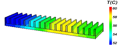
The equation for optimum spacing and height of fins ends up settling out with ~2:1 fin height to space ratio being optimum. One way to make the heatsink more efficient is to increase it’s length along the fins. This is where the PAE-Kx32 is the first to employ a heatsink more than 1-1/4″ long front to back. The PAE-Kx32 heatsink is 1-3/4″ long, which allows an extra 50% more heat dissipation than our competitors. This extra length would interfere with the Gems Products™ SideKX Cover, so we innovated the unique lip in the heatsink which helps reinforce the cover. Since we first introduced this performance enhancing feature, our competition have copied it, which acknowledges the superiority of the original PAE design. The PAE-Kx32 has other design features which have not been copied, and which make it the highest-performance heatsink of it’s volume on the market.