

This page is a collection of thoughts and pictures while rebuilding the Force 12 C-4SXL four-band Yagi, original design with linear loading. If you own an old Force 12 antenna and have contacted the new Force 12 about upgrades and parts, you know how helpful they are, and if you are a US ham having a US source for support and parts is invaluable and Force 12’s designs and quality are excellent.. They are a great company, and I’d love to own one of their new antennas. Of course I have this old one and I couldn’t resist the challenge of rebuilding it!
It seems every ham has their own ideas about how to build and rebuild antennas, and I’m no exception. I welcome any comments from others who have rebuilt their own old aluminum skyhooks, especially these old Force 12 models. All pictures on this page will launch full-resolution versions in a separate window when clicked on.
When looking into the purchase of a multi-band Yagi I was fortunate enough to first purchase and read the report written by Ward Silver, NØAX, and Steve Morris, K7LXC titled ‘HF Tribander Performance – Test Methods & Results – 2nd Edition’ available from Champion Radio Products: http://www.championradio.com/HF-TRIBANDER-PERFORMANCE-TEST-METHODS-RESULTS.2
Their meticulous testing and documentation of results confirmed what I had experienced; that trapped tribanders are not necessarily the best way to achieve multi band coverage, in fact the last triband Yagi I owned was a Moseley CL-33, and I had trap problems with it. In addition it was no better and perhaps worse on 15M than the home-brewed 15M 3-ele beam it replaced.
As a result of reading NØAX and K7LXC’s book coupled with my own experience I resolved to purchase a Force 12 C-4XL or C-4SXL 4-band multi monoband Yagi. After some looking around I was lucky enough to find a classified ad in QTH.com which read “Force 12 C-4SXL and Rohn HBX56 free if you take them down and take them away.” A phone call revealed the situation was a divorce where the non-ham spouse got the house and tower, and she just wanted to get rid of all the ham stuff. A couple of days later I was on the road with a willing friend (thanks David! We had fun in Louisville, eh?), and after a somewhat arduous disassembly headed home with the antenna, tower, and a Yaesu G800SA rotator. The C-4SXL had obviously been in the air for quite a while, the fiberglass insulators had lost all of their gelcoat and were frayed and fuzzy, and all galvanized hardware was totally rusted. On the positive side, all parts were there and the rivets were tight, showing the viability of that attachment method.
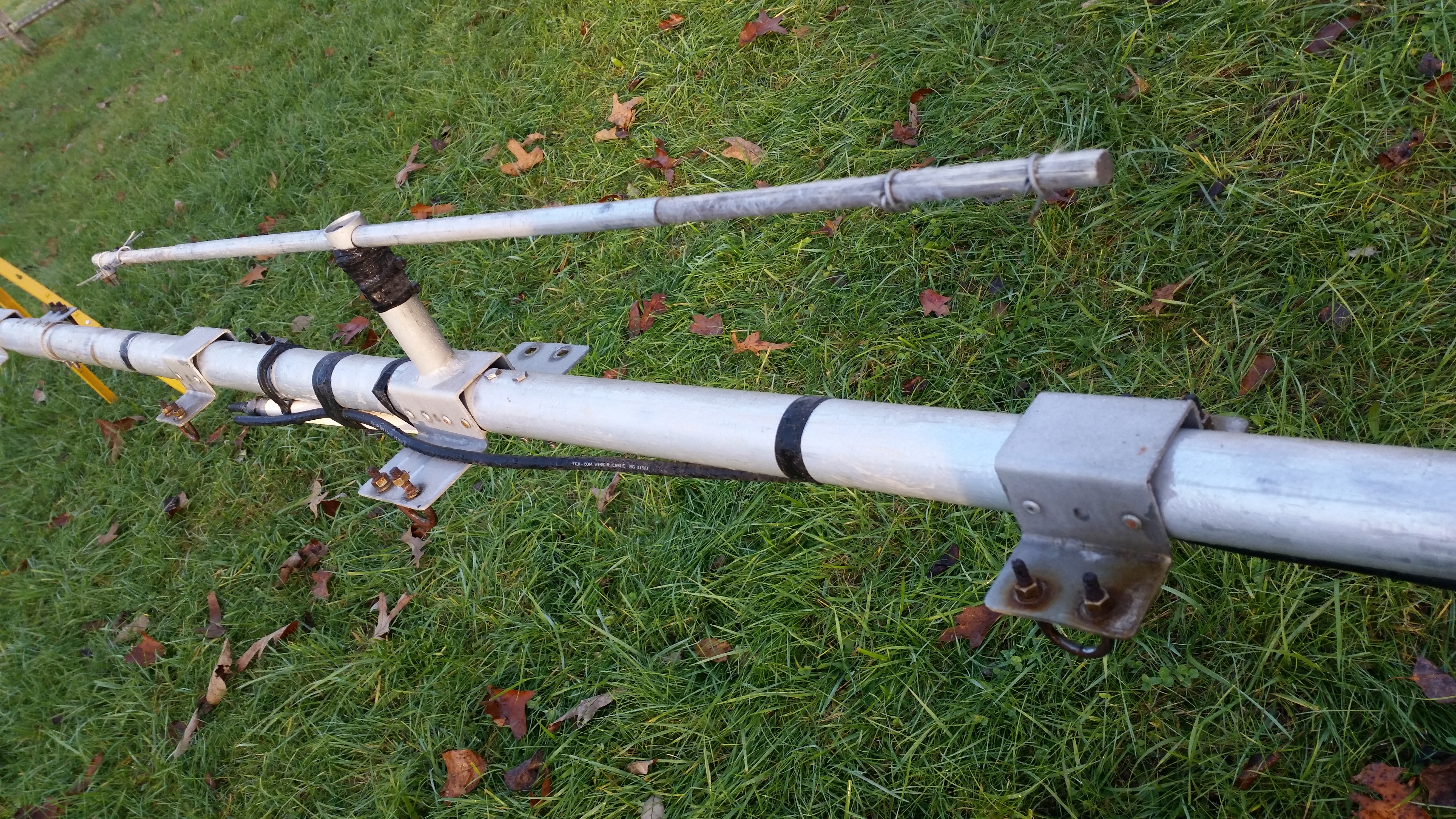
Segue to the present some, um, time later. I pulled all of the parts of the Force 12 C-4SXL out of storage and further disassembly showed the stainless steel (SS) hardware had been installed without anti-seize and much of it galled and broke when I attempted to remove it. There were numerous surprises as well: the small ends of the element were all plugged with mud-dauber wasp nests, and the boom sections were mouse hotels. I flushed all tubing out with water and tried not to blow chunks myself as um, debris came pouring out….NASTY! This picture shows the condition of the boom and other parts when starting the rebuild:
After a full disassembly and cleaning I removed the corrosion from the aluminum parts with 3M Gray Ultra-Fine Scotchbrite Pads, bottles of Loctite Aluminum Jelly: http://www.loctiteproducts.com/p/s_trmt_alum/overview/Loctite-Aluminum-Jelly.htm , wire brushes and a ton of my own elbow grease. (2019 edit: Both the Duro and Loctite Aluminum Jelly have apparently been discontinued. We have used acidic ‘brighteners’ as well like the NAPA brand which work, but they are not as easy to use, and will etch concrete and kill grass when they drip off, so caution is advised) This arduous process took a total of 5 hours, but the results were worth it:
![20151212_085434[1]](https://proaudioeng.com/wp-content/uploads/2016/01/20151212_0854341.jpg)
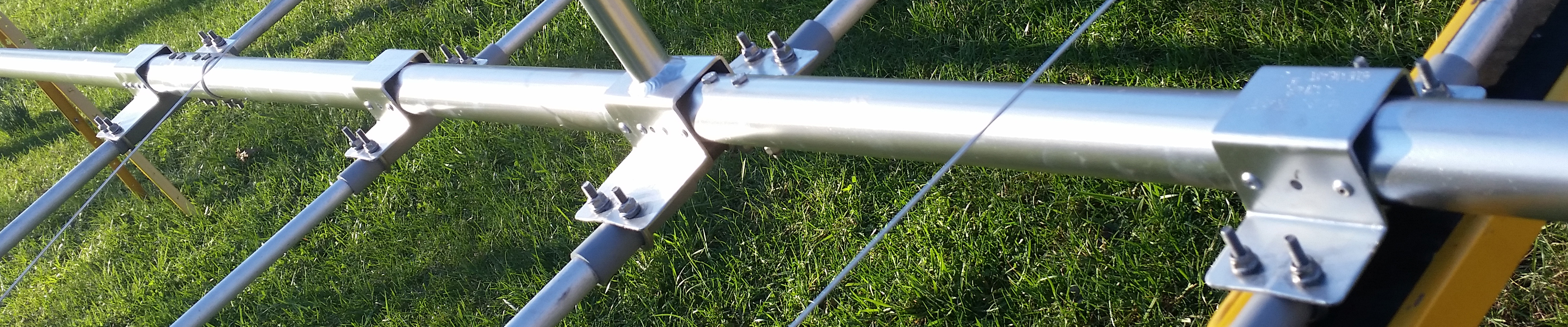
The boom had previously been painted with some very tenacious silver paint which was mostly removed by cleaning, so the end result was clean and corrosion-free, but it looked looked spotty from the old paint residue. In order to improve the appearance and help a bit with future corrosion, I lightly sprayed just the boom and element brackets with Krylon Rust Tough Silver Metallic Enamel (p/n RTA3292). Here is the boom and element assembly after painting:
I originally thought I might switch from the original Force 12 U-bolt and PVC conduit insulator approach for element attachment, to a Stauff-type resin clamp with reinforcement plate like that sold by DX Engineering. A quick calculation showed it would cost $231 + shipping and new holes would have to be drilled in the boom attachment plates, perhaps leading to slop in positioning. Pricing out a full set of new SS U-bolts and PVC conduit came to <$80 including new wide-flange SS Nylock nuts and extra-heavy SS lockwashers, and this convinced me to follow the original route, substituting SS U-bolts for the original galvanized.
After some analysis I believe the original Force 12 method of element attachment simple as it is, would be stronger than the polymer blocks and bolts on the old-style element brackets due to how they clamp the PVC and element tubing directly against the boom brackets and close to the boom. This fully boxes the boom and makes the element and PVC tube into a structural part of the element to boom bracket. This translates the element’s rotation motion into pure shear on the boom rivets, a mode in which they are strongest, arresting bracket rotation and making the whole system tightly coupled and very rigid. It is a clever and minimalist system!
The Stauff clamps suspend the element farther away from the boom, giving the inertial moment of the elements a lever-arm farther away from the center of rotation (the boom) which can induce additional torsion on the mounting plate. Because they are not clamped in intimate contact over a large area of the plate like the original method, they offer little reinforcement to the plate stability allowing the plate to bend. You will note when Force 12 changed to the polymer block method they redesigned the boom brackets thicker, with a bottom plate to take the place of the element’s contribution to rigidity and designed them to be riveted on all 360° of the boom instead of just 180° as the original was: http://www.force12inc.com/pages/parts.html (2019 edit: Force 12 is long gone and currently a few models are being made by JK Antennas). I’m sure it is much better in general and would upgrade to it if it was worth it, but I’m also sure they could not get away with the earlier version brackets with the new mounts.
*** A note about using stainless steel hardware – many shy away from their use due to bad experiences with galling and seizing. I have used both 18-8 and 300-series stainless fasteners extensively in industrial cooling systems exposed to weather extremes as well as complex aqueous chemical mixtures for 30 years. I believe the secret to be consistent use of a high-temperature nickel-loaded anti-seize compound like the Loctite: https://www.mscdirect.com/product/details/94003035 in conjunction with Nylock nuts. The nylon friction member creates a semi-seal at the back of the nut, holding in the anti-seize in a pocket around the threads. In those 30 years I have seldom had a stainless steel fastener system gall and fail when doing so, indeed far fewer than failure of rusted galvanized fasteners by a huge margin. One suggestion when using SS fasteners: wear nitrile gloves: the anti-seize gets everywhere and it is much easier to throw gloves in the trash at the end of the day than it is to get the stuff off your hands, plus some people are sensitive to nickel.***
There is a lot of hardware on this antenna, and I used McMaster Carr to get most of it; numerous SS U-Bolts, flanged SS locknuts and oversized SS split lockwashers and other hardware parts. They are not the cheapest source, on the other hand, there was only the one shipping charge and they showed up the next day. You gotta love McMaster Carr!
The previous owner (or one before them) had painted and taped the PVC pipe section insulators and they were in bad shape. I cut new ones from 3/4″ and 1″ grey schedule 40 electrical conduit and discovered why they were slit lengthwise: the ID is 0.085″ larger than the OD of the aluminum tubing they are supposed to clamp tightly. I ended up milling a 0.125″ slot down the length of each to allow the compression.
I began to investigate ways to replace the degraded fiberglass parts, and certainly new rods could have been purchased however the damage was superficial and did not effect the strength of the rods. I decided to sleeve the exposed sections of the 1/2″ fiberglass rod parts with 3/4″ UV-stabilized marine-grade dual-wall adhesive heatshrink tubing, and used 1″ tubing on the 3/4″ rods. Some testing showed the longitudinal shrinkage of this tubing to be about 6%, so I oversized the lengths accordingly. Here is the final result on one of the 40M element insulators:
![20160105_154632[1]](https://proaudioeng.com/wp-content/uploads/2016/01/20160105_1546321.jpg)
On the subject of the 40M elements; the ‘studs’ as Force 12 calls them, clamp the loading wire to the element at midsection. As I got them, the SS 1/4-20 bolts were all seized in the aluminum studs and all attempts to heat and lubricate them failed, so the bolts were backed out by force. As they came out, so did a lot of the threads in the aluminum stud. A 1/4-20 Helicoil could not be installed, since the resulting hole was too large for a 1/4-20 Helicoil tap. As a result I just drilled and tapped them for 5/16-18 SS bolts, and added lock nuts and lock washers. You can be assured when I installed them all hardware received a liberal coating of the anti-seize, as well as Noalox between all aluminum parts!
And here is the rebuilt and heat-shrink covered linear loading spreader:
![20160102_154333[1]](https://proaudioeng.com/wp-content/uploads/2016/01/20160102_1543331.jpg)
While I was planning the rebuild I talked with Force 12 about the possibility of eliminating the 40M linear loading setup and upgrading to their Tornado coil-based loading. It is a beautiful upgrade, more rugged and higher-Q, not inexpensive but well made at $189.95 ea. * 4 + shipping. A less expensive alternative would be to wind the coils myself and adjust the element lengths to achieve a match, but considering the linear loaded version works well enough and I already had it, I decided to just rebuild them. This picture above also shows the linear loading wire termination technique I decided on. The linear loading wires are 12 gauge Alumoweld, which Force 12 does not carry, so I purchased it from Hy-Gain, their part number 691067: http://www.hy-gain.com/Product.php?productid=691067
The original approach used by Force 12 when attaching the linear loading wire to the spreader was to push the wire through the hole in the fiberglass spreader and wrap it around the spreader rod, then secure it back to itself with two galvanized guy wire clamps. Given how brittle the high-tensile steel core is of Alumoweld wire, the sharp-radius bend at the hole seemed like a bad idea, and dissimilar metal corrosion with the clamps sets in very quickly, not to mention I thought this part of the loading system looked very sloppy and haphazardly designed. Of course it was probably the easiest and least expensive way to secure the wire without special tools. After thinking about how to clean up the linear loading system, I discovered perhaps the only one good thing about maintaining wire horse fencing: you end up owning tools for splicing wire. As a result I already had the solution I chose for the linear loading wire termination. Should someone else decide to do the same, the tools are not that expensive and useful for crimping large sleeves and terminals of many types. Here is a link to one such tool and gritted crimp sleeves: http://www.tractorsupply.com/tsc/search/fence%20wire%20crimping%20tool . This system is strong; I have had a 1200 lb. horse run into the fencing, and the wire did not break at the splices!
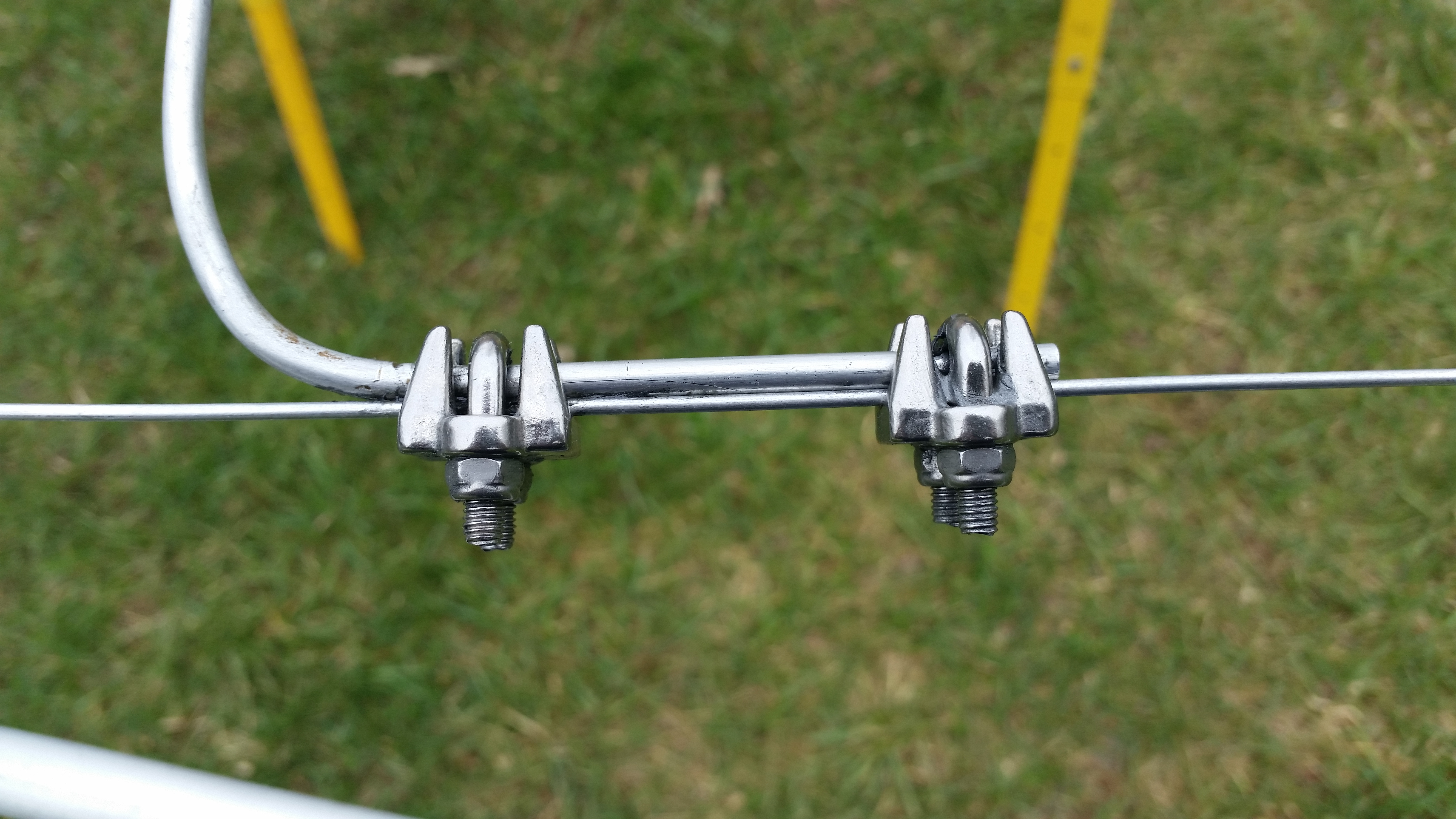
Bending the end of the wire 180° and crimping it into a #2-3 gritted crimp sleeve seemed like a neat solution to terminating the spreader end of the Alumoweld, but initial attempts showed the brittle high-tensile steel core would break when this small radius bend was attempted. While this verified my concern over the bend used with the initial design, it posed a stumbling block for my intended method of termination. This is how I dealt with this problem: I heated the last 2″ of the wire with a propane torch and watched the very end of the wire. When the aluminum there just began to dull at it’s melting point >1200°F, I removed the heat and allowed the wire to cool. This annealed it enough to allow the desired bend radius. Here is a comparison of attempted bends/crimps without (left) and with (right) annealing:

When installing the wire I placed a #8 SS flat washer on the Alumoweld under the crimp to help spread the load on the heatshrink . The final result as seen is far neater and easier to maintain than the original approach:

After installing the linear loading wires I installed the cleaned jumpers using 3/16″ stainless steel guy wire clamps and Noalox, with Nylock nuts and antiseize on the threads of course. If you order the SS guy wire clamps from McMaster Carr, it will have a little U-bolt with M5x0.8mm threads. It looks like a #10-32 thread but it is not. Buy new M5x0.8mm SS Nylock nuts to go with it! Here’s the result:
The final step in assembling the C-4SXL was mounting the baluns. I kept the EB-1s as they have >1kohms impedance from 7MHz upwards, which is acceptable. The previous owner had merely taped them to the boom, which I did not like from a stability viewpoint, and tape looks like crap. I located some SS conduit hangers and joined them, then mounted the 40M balun as shown in the upper picture below. The 20M/15M/10M feedpoint balun requires the hangers to drop the balun by at least 3/4″ to clear the 15M driver as shown in the lower picture.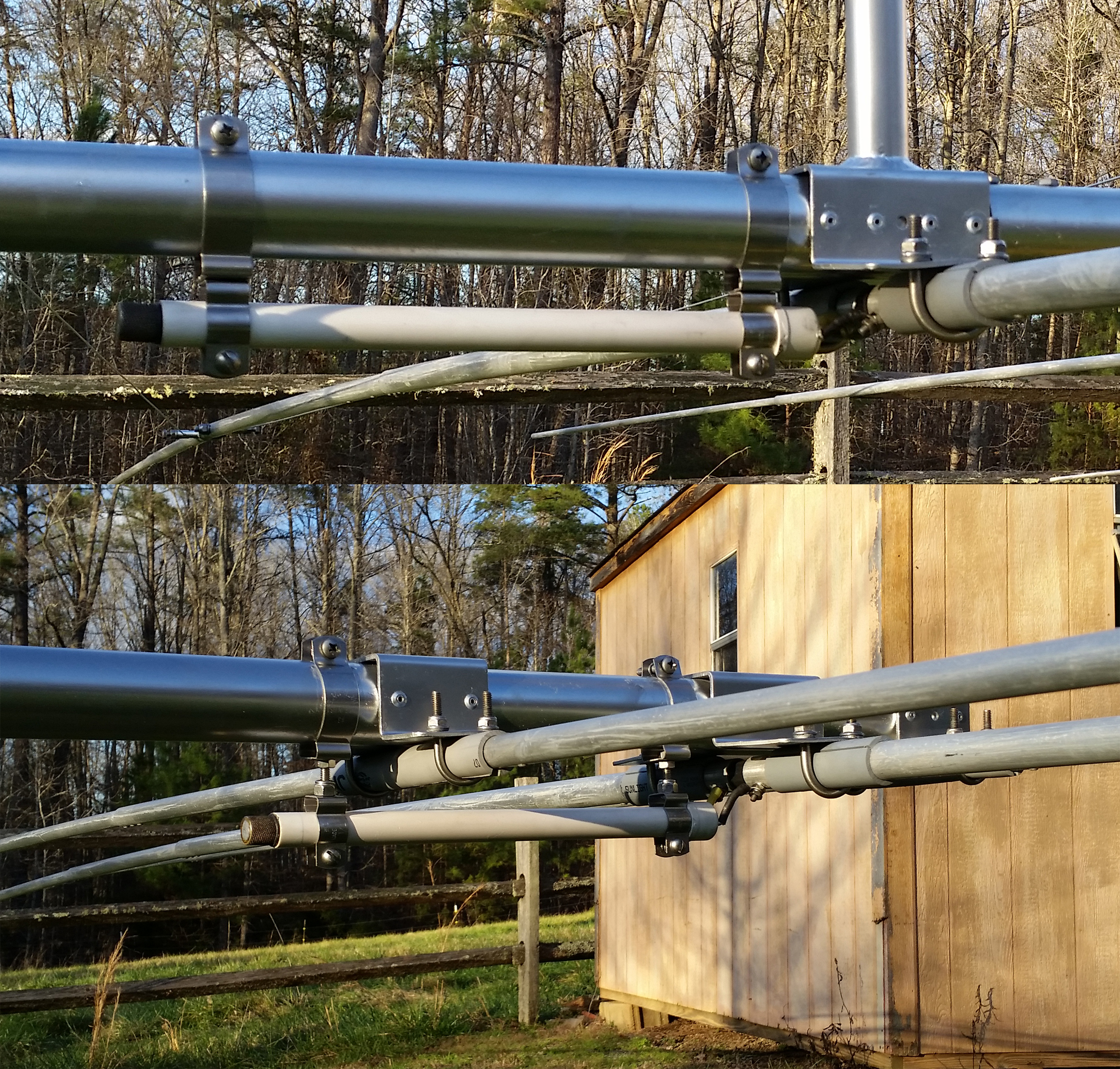
This last picture shows the C-4SXL rebuild results, it came out pretty well for a 20-year old antenna. I’m looking forward to raising it and seeing how well it performs! Another Force 12 original will soon be back on the air…

Nice work, Howie!
My new-to-me C-4XL also needed a bunch of work and my work was almost identical to yours. The only thing of value I can add is that the Pop rivets I used (from McMaster-Carr) were “corrosion resistant blind rivets”. This I learned after inquiring the old Force 12 company and then the Tower Talk email reflector.
I’ve had mine up since 2012 and found I mostly don’t need to run an amplifier. Like some cameras, it’s a “point and shoot” yagi.
vy 73,
Bryan WA7PRC
I’m not sensitive to nickels, but a fiver will get my attention!
I’ve checked several times and never found a problem mixing 5nn and 10-32 hardware. Can be convenient on a weekend.
You could just put a scrap of wire in that crimp to fill it, but the annealing is pretty.
I bought a Chinese crimper, fractional sizes, and it seems as good as Nicopress. I make 3/16″ wire rope slings, with single sleeves, for tractor work and none have let go!
Nice job! I’m anxious to hear it!
73,
WL
Thanks WL!
The crimper I have was most likely bought at Tractor Supply, and there is little there not Chinese, so….yes, the crimps do not look as uniform or pretty as using an official Nicopress tool, but they are strong.
Thank You! I have a C4-SXL sitting in the yard right now (and it is a mess). I have been trying to figure out how to approach a rebuild (I sure miss the 2-ele 40m). This detail helps a lot!!
73, Bert – K4AR
(I also have the sister WARC-7 yagi on another tower)
Thanks for the comment Bert! Good luck with your rebuild, it is an interesting challenge!
Hi Bert,
It is a fun project, let me know if you need any info or supplies.
Cheers & 73,
Howie – WA4PSC
I was’nt sure how to approach my rebuildt,but after i read what you did, i feel inspired to tackle the job.
Well done.
Congratulations.
73,Rayne ZS1RM
Thanks for the comment Rayne!
Let me know if you have trouble finding any of the parts described in the article, I’ll be glad to help you.
Good luck with your own rebuild.
Howie – WA4PSC
Hi Rayne!
The job is not difficult for sure, just a lot of different details to pay attention to. Let me know if you have any questions or have difficulty getting any of the supplies. We regularly ship worldwide every day.
Cheers & 73,
Howie – WA4PSC
Hi!!
Thanks for share your rebuild.
Im restoring one.
Have a Question about the 40 meters reflector element: Does have a bridge (jumper) at the central feeding point? (between two sides)
Not sure about this point because no manuals.
Regards.
Hi!
The 40M reflector has a very short jumper between the two element halves, the driven has a loading coil not shown in the pictures.
Good luck!
Howie – WA4PSC
How many turns and diameter of 40 meter coil? I read it somewhere but cannot find it now..
Putting up and restoring my C-4SXL after quite a few years of not being used.
Hi Bob,
Sorry for the long delay in replying. My coil is 2.745″ ID and 3 turns, made of 0.25″ tubing. flattened and drilled to go over the terminals. Hope this helps!
Cheers & 73,
Howie – WA4PSC
Hi Howie – WA4PSC,
I was very fortunate to get the original Boom which is 9.5 meters long and the 2 elements for 40 meters from a fellow Ham that live in South africa.
I also got a booklet from another Ham, which explain it step by step with pictures how to assemble the antenna. I had to assemble the antenna on top of my double-storey roof because I did’nt have enough space on the ground.I was battling to get the wire for the linear loading and then I decided to use a 6 mm solid aluminium rod, which was avilable at one of the local factories selling aluminium tubing.My Force 12 C4 XLD is up and I must just get the SWR right.If there is anybody who need the paperwork, you can give them my e-mail address and I am willing to forward them a copy.Thanks for your inspiration.
I have a 9 element force 12 antenna and have downloaded a few manuals however they are for 7 element force 12. I have all 9 elements marked in the order in which I disassembled them however I can’t remember what side of boom to start attaching them .. any help would be much appreciated. Thanks Dave K7JFK
C4sxl source for material for “black” element insulators
thanks
Hi Bob,
Those ‘black insulators’ are the original fiberglass rods which had totally lost their gelcoat, so I melted dual-wall marine heat-shrink tubing over them. The marine grade heatshrink seems to be much longer lived, and is available on Amazon among other places.
Cheers & 73,
Howie – WA4PSC
Hi Howie,
I am really struggling to get SWR right of the 40 meter of the Antenna
How long must the “coil” wire be that connect the 2 sections of the Boom.
I tried moving the jumpers to get the SWR right ,but I was un-successfull.
Rayne ZS1RM.
Hi Rayne,
Here is a picture of the C4SXL feedpoint, note the hairpin matching coil mounting maybe 3″ (75 mm) away from the feedpoint;
Of course the reflector halves have a very short wire connecting them together.
Good luck,
Howie – WA4PSC
Hi,
I just raised my C4XL after performing a rebuild very much like what you describe. It came out very nice.
She is back up at 70’. 40 tunes well, 20 tunes great at less than 1.2 SWR across the whole band. However; 15M & 10M are both just over 3 SWR across their bands.
I’m wondering what your 20/15/10 SWR values are?
73
MacCoon.
Currently my C4SXL is at 4′ and has high SWR on all bands…lolol, it is on the ground awaiting tower work. Did you disassemble the 15 & 10 elements or leave them in place during the rebuild? All I can imagine is they somehow were changed from stock…
73,
Howie
Found the problem …. my 20M driven and reflector were installed backwards. Repositioned the elements and now all is perfect.
73,
Brian AB2BA
None of my elements were disassembled during the rebuild. The 15 & 10 element mounts were cleaned and the element assembly was not modified in any way from the original assembly. I do have a 2M vertical plane 11 element beam about 6′ over the C4XL. Maybe that is causing a conflict.
Hi Howie WA4PSC,
Thanks for the drawing showing the position of the coil.
I did my Force 12 C4XL during my December 2017 holidays and I can report back that it is now working 100 %.
I made 3 mistakes previously, that made me battle to get the antenna working.
1. I had 2 other 40 meter wire antennas below the Beam and everytime I put the Antenna analyser on it picked-up the other antennas as well.(mutual coupling )
I mentioned it to fellow Ham and he said that I must lower those antennas and everything changed for the better.
2. The centre spreader where the linier loading wires were mounted on was only 600 mm wide instead of 1220 mm and that made it difficult to set the resonnent frequency.
After I made it to the correct length, I could choose where I want to set it (higher or lower in the band.)
3.The spacing of the turns in the coil was also very important ; 3Turns ; 13.2 mm apart with a 0.25 inch copper pipe ( as your drawing show )
I am now getting 59 +10 & +20 reports from Hams like KE5EE,K6MYC , W7GI and many others from the USA.
Thanks guys.
73’s
Rayne ZS1RM
Hi Rayne!
That’s great news and thanks for the tips! These antennas though an older design are still high-performance.
Cheers & 73,
Howie – WA4PSC
Hi thanks for the write up!
I also have a used Force 12 with 2el on 40. Mine was missing the linear loading wires. I have 14 gauge aluminum electric fence wire I was going to use for the linear loading. I was wonder what lengths do I need for the wires? Also planned on Using the same for the shorting sections but noticed yours is rigid like tubing or rod? Using regular wire is not recommended? Does the shape of these tuning stubs make difference and what are the total dimensions for the linear loading wires. It appears the reflector and the driven element are of the same dimensions, is that correct? I understand that this 40 meter linear loading is difficult to tune and requires being tuned at height. I hope to get it as close as possible and avoid many trips up and down at 54ft. I have no other antennas to detune the antenna. Of course mileage often varies. Where should I start with this linear loading wire dimensions?
Hi Brian,
The suggested starting dimensions as well as all linear loading instructions are found in the EF-240 manual I have available at this URL:
https://proaudioeng.com/wp-content/uploads/2018/03/EF-240-SN-manual-2.pdf.
I would hesitate to use aluminum electric fence wire, because the linear loading also serves as a truss for the long 40 M elements, it will stretch and gradually lengthen with temperature cycling and time. Alumiweld is available direct from HyGain here:
http://www.hy-gain.com/Product.php?productid=691067
The lengths are set by the distance between the center fiberglass spreader and the studs on the element at the split point. Following the instructions will let you set them up correctly.
The inverted “V” tuning jumpers have 4″ legs bent at a right angle to clamp to the linear loading wires, and between these legs they are 45″ in length, so before bending to shape they are 53″ overall length. Because the linear loading wires converge in a “V” shape at the element half split point, you merely make the “V” more or less spread open to allow the tuning jumpers to line up.
Remember the reflector halves get jumpered, and although I have heard of people doing without a hairpin match at the driven element feedpoint, it is recommended.
Good luck!
Howie – WA4PSC
Hi Howie,
Great article! My crusty old C4 is lying in my driveway, with no place for my wife to park. The U-bolts are so rusty, it’s difficult to tell what sizes they originally were. It looks like I need 1.5″ ID, 2″ ID, and 2.5″ ID… do you still have the McMaster-Carr PNs or exact sizes?
Thanks, Bruce K3NQ
Hi Bruce,
On my C4SXL the 10 and 15 M elements use 1/4″ x 1-1/8″ ID u-bolts (McMaster p/n 8896T104), and the 20 and 40 M elements use 5/16″ x 1-1/2″ ID (McMaster 8896T126). I guess it is possible N6BT changed the design at some point…
Cheers & 73,
Howie – WA4PSC
Howie,
Wonderful article and very informative. I recently picked up a NIB C4XSL from a gov auction site….still trying to wrap my head around how a school district would have had one of these, unless the school ham club sponsor robbed a bank 🙂 Only thing missing seems to be the manuals, which I found online, albeit with poor pictures. Your EF240S manual link was great! Your rebuild details, and the questions and replies offered herein, have really helped me understand my pending initial build much better. Here’s hoping we find a house with enough yard this year to put this puppy up! Thanks again and 73! Cliff W3KKO
Hi Brian,
I wonder if you got the linear loading sorted out on your side.
Like I said I used a 6 mm solid aluminium rod , which also helped to pull the elements in line with the other elements for 20,15 & 10 meters.
On the end further from the boom it must stick out about 6 inches as stated in the manual and near the boom the ends must be 1200 mm apart.
You can than move that V- sections that you bent further away fro the boom.
For the driven element mine is about 300 mm from the boom and for the reflector it is 100 mm from the boom.
The SWR on the other bands is perfect.
the linear loading is just to get the SWR right for the 40 meters.
73’s
Rayne ZS1RM.
Howie, greetings from Washington, DC. I happened to be in the midst of a roof repair / redone where my F12 C3S (with 40M add on) sits on a Glenn Martin . So I took it down in preparation for the work to be done. In the midst of removing nuts / volts, well, as everyone done it, noticed corrosion, etc. This is when I searched / found your interesting documentation about how run maintenance on your system.
Do you have a part list (PVC, Heat Shrink, hardware) in hand with vendors, etc. that you can post? Although I gathered most of what I need by reading the document, comments / replies, it would be of immense assistance for those new / old readers to have all the stuff in one place. Just a thought / suggestion.
73
Rafael / NN3RP
Nation’s Capital USA
Does anyone know the correct size for the rivets? I mean for the elements mainly.
I placed an order with McMaster for some of the hardware but I wish I know the rivets size to complete the job. I know is as easy as removing an element and taking out the rivets then off to my local hardware….but.
Rafael / NN3RP
Hi Rafael/NN3RP,
I used 4 mm aluminium rivets on my elements
You must also make sure that you use Penetrox ( aluminium grease ) on all the joints , then it will be easy to remove the pieces at a later stage.
I wanted to send you a picture of my antenna, but I could not get your Email address.
73’s
Rayne ZS1RM
Force 12 is a great antenna . I have a Mosley xlr 7 element 6 thu 40 at 62 ‘ with hazer g45 tower . Near zero swr all bands out of the box . I like Mosley testing for swr and the color code . like I said ore 12 is great .
Howie,
Thanks for a great guide. My C4-XLD has been on the ground for five years. We moved from Colorado back to California in 2015 and then to this place in 2017. I just finishing pouring 7.5 cubic yards of concrete for my US Towers HDX-555. I intend to erect a DIS 7-3 (3L 40 meter yagi) on top and the C4-XLD below it. I am going to start the rebuild process (spaced between the XYL chores).
Note that I have a remote switch box that switches two coils for the driver. This way I can cover all of 40 with low SWR. I will post before I erect this berast (projected for August 15, 2020 CE).
Thanks again to all for your informative comments and suggestions.
Semper Fi,
Tommy K6YE
DX IS and CW RULES
HI Tommy,
I’d love to see the end result of your install, thanks for the post!
Howie / WA4PSC
Howie,
The tower is going up Thursday, August 13, 2020. I am ready to deal with Murphy’s Law.. Unfortunately after five years of limbo, I cannot locate the element U-bolts (10 smaller and 8 larger) or the two (2) boom-to-mast plate ones. I can order everything from McMaster-Carr but need sizes. In the meantime, I am drilling out all element-to-element rivets and reattaching along with Noalox.
Any help you can provide will be greatly appreciated.
Semper Fi,
Tommy – K6YE
DX IS and CW RULES
Hi Tommy,
I am unable to pull up that McMaster Carr order, it was from 5 years ago, sorry. McMC has such a wide selection:
https://www.mcmaster.com/u-bolts/u-bolts-6/
You should be able to find them pretty quickly by measuring the diameter of each location and reference to the ID column. The appropriate Nylock nuts are here:
https://www.mcmaster.com/nylock-nuts/18-8-stainless-steel-nylon-insert-locknuts-10/
For the boom-to-bracket and bracket-to-mast nuts I ordered wide flange nuts:
https://www.mcmaster.com/flange-nuts/flange-nuts-5/18-8-stainless-steel-flange-nuts-8/
These nuts, in addition to incorporating a flange to spread clamping pressure, are taller for more thread engagement which allows for higher clamping force with a given torque.
Remember to use a good high-temp nickel anti-seize with all of the SS hardware:
https://www.mcmaster.com/nickel-anti-seize/
I used their p/n 1028K63, and you should have little problem with seizing in the long run.
Good luck, and have fun! I found the project very satisfying, once I resigned myself to just doing it right without time pressure.
Cheers & 73,
Howie / WA4PSC
Howie,
Thanks for all of your assistance and encouragement. The final inspection for the tower went through without nary a hitch. My Inspector was a real treat.
I will post as I get things completed. The first order of business is to get U-bolts and nuts ordered and element disassembly/reassembly.
Semper Fi,
Tommy – K6YE
DX IS and CW RULES
Howie,
I just refurbished a C4S using a lot of the methods in your rebuild. Especially the mounting of the baluns and the linear loading wires on the 40m element. I am having some problems since the VSWR is 3.5:1. I have a matching coil (i.e. hairpin matching coil) but I cannot find the ID of the coil anywhere. I understand it is three turns but it looks like the ID is pretty wide.
Can you help?
Fred
Hi Fred,
On mine the hairpin coil is three turns wound on a spray can ~3″ in diameter.
I hope this helps,
Howie / WA4PSC
I’m about to pick up a used Force 12 C4 antenna and this article is an excellent read. It’s given me many ideas to implement in the rebuild of the C4. I’m not sure of the full model # but the antenna has 8 elements including the 40m DP. Should be a fun fall / winter project.
Bob. K2RET
Hi Bob,
Thanks to N6BT who designed them, these antennas are great performers, good luck with your rebuild!
Howie / WA4PSC
Hi Bob K2RET and Howie WA4PSC,
I just want to share something with you’ll.
I was very pleased after I managed to get my 2 element for 40 meters to work and I want to say thanks for the inspiration I got from you guy’s with this article.
I then purchased a KLM 34XA, which I refurbished and I used it for 20,15 and 10 meters.
I only got 1 tower and I was forced to mount them on the same tower.
Most of the guys said that the spacing must be about 4 meters, otherwise it is not going to work,
I decided to remove the 20,15 and 10 meter elements from the Force 12 C-4XL ,because I was worried that the elements will cause interference with the elements on the KLM 34 XA.
I did not have 4 meters on the upright pole, so I mounted the Force 12 just 500 mm above the KLM 34XA.
I looked at the 2 element for 40 meters and I decide to change it to a 3 element for 40 meters because I had 4 meters in front of the Driven element that was already there.
I then made the 3rd element the same length as the other 2 elements ,but I joined the 2 halves together, the same way the Reflector was joined.
The difference come in when you tune the Linear loading jumpers; for the Reflector you move the jumpers 100 mm from the boom and for the Driven element they are 305 mm from the boom, so I decided to move the jumpers for the Director 200 mm from the boom.
Normally you got a 5% slope in Yagi’s from the Reflector to the Director, but I allowed for that when I spaced the Tuning Jumpers differently from the boom for each element.
If anyone need some more information ,they can contact me and I will send them some pictures.
I thought that I want to share my experience that I had with you’ll.
Everything fell perfectly in to place and the Antenna is working like a dream.
Rayne ZS1RM,
I am very interested in seeing your pictures and information on how you added a director to your stripped down Linear Loaded Force12 C4SXL.
I already enjoy a large Hygain TH7DX tribander up on top of my tower. I dont want to bash the Force 12 I am limited to a total height of 56 feet. After auditioning both antennas, I found that for my application, the TH7DX is just a significantly greater performer.
It appears quieter, seems to have much better front to back, tighter beamwidth, and when compared the TH7DX looks as if it has much greater forward gain.
Of course the TH7DX is limited to only the 3 conventional bands 10,15,20.
The thought of using the Force12 as a basis to build a different antenna has often been on my mind. I”ve been contemplating making mine into a similar “shorty-forty” type of design.
Similarly, my intial thought or hurdle was what to do with all that extra boom and having to rebalance the whole mounting and such. I didnt want to get too carried away and destroy the whole antenna, just in case I wished to return it back to stock configuration.
I probably could get away with a stacking spacing of between two or three meters between both of the antennas on my mast. Wind loading would likely be questionable. However I have a telescoping tower that is motorized and never keep the tower extended when not in use.
Too much is never enough! hi hi.
Brian K6LPM
southboundsuarez@hotmail.com
Rayne, I am very interested in your 3 element 40 mtr monoband conversion to the Force 12 C4xl …
I have a Force 12 laying upon the ground and a Hygain TH7DX
Upon the tower. I would like to modify and stack the Force 12 along with my TH7DX
I had replied once before but do not see my reply anywhere here.
So not sure if my request is published or if I am posting correctly or in the right place. Obviously your direct email is not published.
Hallo to all , i have a little problem ….i have F12 C4SXL Yagi and i nedd to replace the 2 Balun wich kind of balun i have to buy?? because in Italy i do not find true info about that…
Mny thanks for answer
73 de IW4BLZ Maurizio
Ciao Maurizio,
Anche io ho la stessa antenna che sto sistemando.
Va bene qualsiasi balun 1:1
Sono ottimi quelli che costruisce IZ8CGE – Franco
IK8TEM
Hi Howie.
Where I can find wire 12 gauge Alumoweld?
I look at MFJ and don’t find.
Thanks
PS. Your antenna looks amazing.
73’s
Mauro ND1M
Hi Mauro,
I’m afraid MFJ no longer offers Alumoweld and I’m not sure who else carries it, sorry.
Cheers & 73,
Howie / WA4PSC
Rayne ZS1RM
Reply to Brian K6LPM
I send you a email today and if you got any other questions you can email me.
I had some very good signal reports, since I added the Director to make it a 3 element for 40 meters
I will send you some pictures in a separate email
73’s
Rayne ZS1RM
Does anyone here know the difference between the C4E and the C4SXL?
Hi Michael,
The C-4E is a C4 (2-elements 20-10 m, dipole on 40 m) with an extra 10 m reflector added behind the 15 m rear driver. The C-4SXL is a 4-band , 2 element per band shortened 23′ boom version of the 30′ boom C-4XL.
If you would like a pdf of the old Force12 catalog, email me at: info@proaudioeng.com.
Cheers & 73,
Howie / WA4PSC
Hey Howie, came across your blog right after taking mine down for the first time in a dozen years. Its never had a rebuild, just a balun change so the hardware itself has been up for 24 years now. The upgrades are pretty similar, all ubolts will be changed, the PVC insulation will be changed, I opted for Balun Designs 1:1 baluns for both bands, along with the mounts. I also need to replace the crimp ubolts on the linear load and the truss cable. We retrofitted a standoff instead of using the mast, it worked great.
My question involves the rivets. I ended up with 2 bags of rivets after originally building the antenna, so I’m guessing the smaller size is for the 10/15 and the larger size is for the 20/40 elements themselves. I was wondering if you had the size for those. Additionally, all of the rivets in the 2nd the last boom to boom coupler have failed and disappeared, to the point that the 40 and 20 reflector were rotating together opposed to the rest of the antenna. Also, all of the 40 and 20 boom to element brackets have either lost their rivets completely or are showing aluminum rust where they’ve waddled out and are about to fail. So my main concern on the rebuild is obviously going to be these rivets. The coupler is bolted on one side, but riveted on the other. Should have just bolted both sides. Would you happen to have the size for THOSE rivets as well? They’re clearly larger than the ones included for element building.
Thanks again for the blog and great ideas and information
Charlie
N5WE
Hi Charlie,
Wow, your C-4SXL must have seen some very high winds. Mine spent most of it’s life in Indiana and none of the rivets were loose, so I do not have any rivet size information.If the holes are ovaled or wallowed out, your idea of replacing them with bolts is certainly feasible, or perhaps drilling the holes to the next rivet size?
Good luck!
Howie / WA4PSC