
There are many posts in both audio and amateur radio groups regarding the unavailability of original power switches for amplifiers, especially high-powered units. In one case there is a lack of availability of the Oak AC power switches for the Drake T-4XB transmitter, which are custom rotary switches attached to the back of a CTS rotary switch. Since I own several large audio and amateur radio power amplifiers which are out of production I knew I had to forestall the failure of those original AC power switches. For decade or so we have offered a comprehensive AC power switching device/power strip: https://proaudioeng.com/products/pae-2900-remote-power-relay/ which incorporates a 555-based soft start circuit which has proven to be extremely reliable, but I needed to make a stand-alone soft-start circuit for embedded applications. I decided to look at the options available once again and see if a different approach would be an improvement which led me down several rabbit-holes investigating soft-start, or as some call it two-step start circuits.
What is the Problem ?
The problem soft-start circuits are used to remediate is the very high surge currents when many devices are first connected to AC power. This is due to the low impedance many devices present to the AC line when they are first energized. In the case of an AC motor this is due to the very low stator impedance presented by a stationary rotor. The initial current drawn when a motor is energized is close to the maximum locked-rotor rating and gradually drops as the rotor gains speed. In the case of equipment with bulk-storage capacitors in DC power supplies like our ham gear or audio amplifiers, whether transformer isolated or not the initial impedance of the capacitors when discharged is quite low, rapidly rising as the capacitors charge. With both motors and DC power supplies the initial current pulse can be ten or a hundred times more than the steady-state current the equipment draws when running. This high current can damage switch and relay contacts as well as causing unwanted momentary drops in the AC power line, blinking lights and perhaps disrupting other equipment. Additionally when removing AC power the energy stored in the inductance of motors and transformers is open-circuited on the primary side causing extremely high voltages to be developed which can cause contact arcing and damage.
Testing Procedure
In order to research the issue I decided to I purchase a stand-alone soft-start kit from Rod Elliot’s excellent ESP site (https://sound-au.com) and used a Drake T-4XB amateur transmitter with it’s companion AC-4 power supply as the guinea pig for testing. I utilized my trusty Tektronix P6042 DC-50 MHz Current Probe to investigate the magnitude of inrush currents into the AC-4. The P6042 has magnificently flat response in it’s passband but is specified to only 500 mA. Since I was expecting currents as high as 100 A, I needed a current divider and in order to pose minimal disturbance to normal operation of the AC-4/T-4XB I chose a 0.1 Ω series resistor for the current sensing. I paralleled it with a 100 Ω resistor pair I matched to exactly (well less than 1% off) 1000 times the measured resistance of the 0.1 Ω resistor. I measured all of the inrush currents on the 100 Ω leg of the current divider so the dynamic current range using the P6042 now extended to 500 A which should be sufficient. Those sticklers among you will point out that the parallel pair is now actually 100 uΩ less than 0.1 Ω so my ratio is off….well I decided that 0.1% error was close enough for this test and the following calibration removed that error anyway.
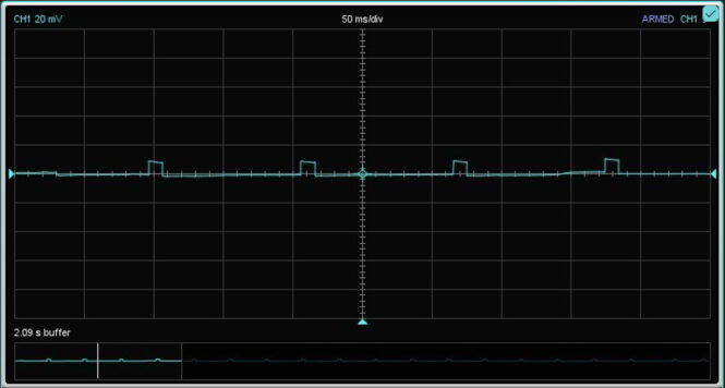
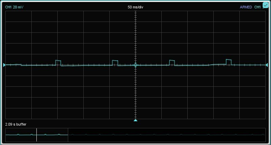
I fed the output of the current probe amplifier into a Focusrite Scarlett Solo analog to digital converter running a 192 KHz sampling rate at 24 bits of resolution, and observed the resulting waveforms in REW (Room Equalization Wizard) because it has an oscilloscope function which is easy and quick to set up. In order to calibrate the software I fed a 50 amp power supply through the current sampling resistor array into an electronic load. Since the Focusrite setup is flat to only 10 Hz not DC, I set the electronic load to create 10 A transient pulses 10 ms wide every 110 ms:
With the setup calibrated for 5 A minor vertical divisions, 25 A major vertical divisions I inserted the setup in the AC input of the AC-4 driving the T-4XB. I monitored the 650 V B+ in the AC-4 to ensure each turn-on surge would be from a fully discharged state. Capturing worst-case inrush current is a crapshoot, since depends on several factors: what polarity of magnetizing current was present when the AC was last turned off, and where in the 60 Hz cycle I re-applied power. Worse case would be if it was turned off at the peak positive or negative part of the current cycle, and then power reapplied at the opposite-going zero crossing. All of this is to explain why when turning the T-4XB on by hand the resulting surge current is not necessarily worst-case, but many tries should show something nearly worst case. With this caveat in mind here is one of the worst case inrush current peaks captured:
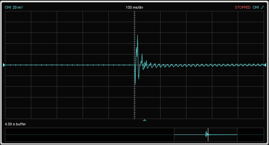
At +70 and -44 A peaks, these represent a pretty high load on the small 5 A rated Oak rotary switch on the T-4XB and these OAK switches are a pain to replace if you can find a replacement. In order to quantify the effectiveness of the time-delayed resistive soft-start approach, I then installed the ESP Soft Start unit and re-ran the series of tests.
Here is the final turn-on current waveform after installing the circuit:
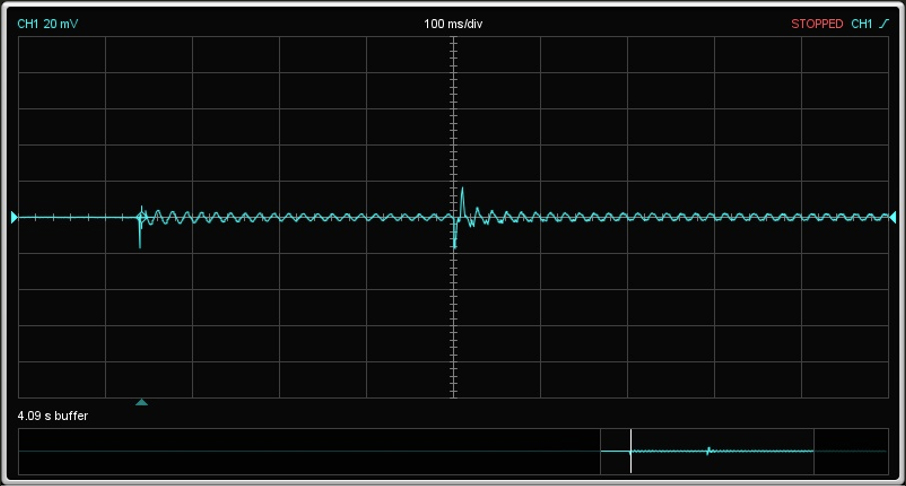
As you can see the initial power-on has a minor surge of -20 A, followed by 360 ms of capacitor charging and then the full line voltage relay closes which has it’s own +/- 20 peak currents. While this may not be the vast improvement you expected, remember these peak currents were now handled by relay contacts rated at 23 A continuous, 100 A surge. The Oak switch in the T-4XB merely applied AC power to a 2 watt supply driving the soft-start circuit. I tried putting the current waveform of that supply on this scope screen…but the current was too low to let me trigger and display it. On my Tek scope the switch current peak looked to be ~+/-50 mA, and at 120 V it is above the oxide puncture voltage with enough current to keep the contacts clean without eroding or overheating. Bottom-line: once I install a soft-start module in the AC-4 I expect the Oak switch to outlast me, and if a relay fails it is easy and cheap to replace.
The kit from Elliot Sound worked well and I can recommend it for applications where there is sufficient space and 10 VAC power available, or if enough room exists to install a small transformer. Unfortunately for my application it’s form factor would not work in the Drake AC-4 especially as it requires an external transformer for power, so I decided to build a small all-on-one PCB module based on our PAE-2900. The design has been simplified and reduced in size in order to fit the AC-4 and other small spaces, and it is now available as the PAE SofStart™ module. Production expected Q1 2023, contact PAE at info@proaudioeng.com for details.
If you are interested in the concept of soft-start circuits, here is a summary of my investigation into them:
The Ideal Soft-Start
The ideal soft-start circuit would monitor the inrush current when power is applied and limit it to some desired maximum current by ramping up the applied AC voltage to the load slowly. Once the load current had stabilized it would take itself out of circuit to allow full AC power to be applied to the load. When power is removed the ideal circuit would instantly revert to the initial soft-start condition awaiting the next power application, allowing it to soft-start in the case of a short power interruption as well. There are several methods which have been developed to attempt a soft-start circuit:
1. NTC (Negative Temperature Coefficient) thermistor also called Inrush Current Limiters.
These can be inserted in series with the incoming AC power. This is perhaps the most simple method and one used since the 1930s to limit inrush current.
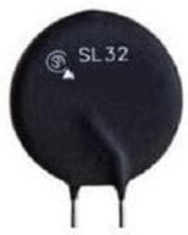
NTC Thermistor
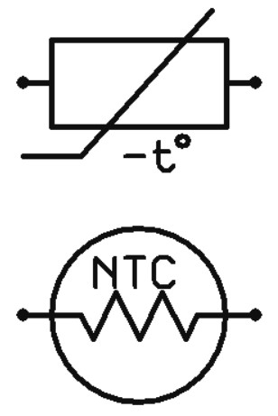
Schematic Symbols
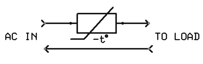
NTC Thermistor Soft-Start circuit
These NTC thermistors have high resistance when cold, so when current begins to flow they warm rapidly, and given their negative resistance vs. temperature characteristic, their resistance rapidly drops to some low value. They end up establishing an equilibrium resistance where their R x I (resistance times the current through them) results in some stable and usually high temperature.
Pros: Cheap and simple
Cons: The heat can cause degradation of other components nearby, the equilibrium resistance may be high enough to cause power supply droop under load, and the heat generated represents a drop in efficiency which may not be tolerable. In addition, they retain heat after power is removed which can cause problems if the power is rapidly cycled. In this situation they are still in a low-resistance state when power is re-energized and therefore they allow large surge currents to pass.
2. Time delayed relay switched resistors.
These circuits use a relay contact with a current-limiting resistor across it which is open when energized. Many of these circuits upon application of AC power merely initiate a short time delay typically tens or hundreds of milliseconds, after which the relay contacts close shorting out the current-limiting resistor.

Relay (case removed)
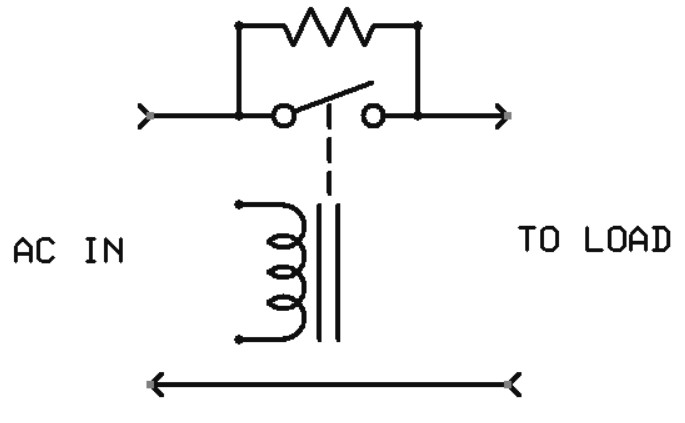
Relay Soft-Start circuit
Some of these circuits substitute a NTC Thermistor for the current-limiting resistor. These circuits continue to use power to keep the relay closed after activation.
Pros: Very low series resistance when relay shunts the resistor or thermistor allowing full power to load, little heat generated, if the circuit drops out quickly enough when power is removed, soft-start operation is preserved during short interruptions (not when an NTC Thermistor is used though…). Also exact current limit and timing can be set by choice of components.
Cons: Higher component count and cost, potential for relay contacts to fail which may cause resistor to overload and fail.
3. Pulse-Width Modulation (PWM).
This method employs PWM to gradually ramp up the effective power using a pass element such as a triac which replaces the NTC Thermistor or resistor. The triac can be controlled by a circuit which either has a fixed ramp time, or which senses current and ramps up the duty cycle proportionally.
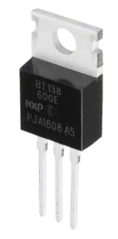
Triac
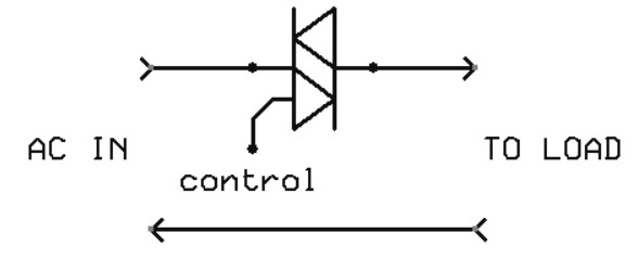
Triac circuit
Control of the triac can be done simply with a few components directly on the AC, or by opto-coupling and employing a DC control circuit. One of the best ways is by utilizing dedicated phase-control ICs like the U2010B. This IC offers many safety and performance options over a simple control circuit.
Pros: Little heat generation due to the pass element triac being either fully on or off, very low power loss once fully turned on, control can sense current and protect against overloads, and restart instantly if power is cycled, protecting the load.
Cons: higher component count and cost, non-zero voltage drop and a triac is fragile with regards to handling transient events compared to a relay. The sharp trailing edges of the PWM waveform cause high voltages to appear at the transformer primary when it is open-circuited. These can also cause ringing in the transformer or other noises during ramp.