(special deal for IC-705@groups.io and FB IC705users members)
Price: $59.90 Shipping Status: Immediate, In Stock
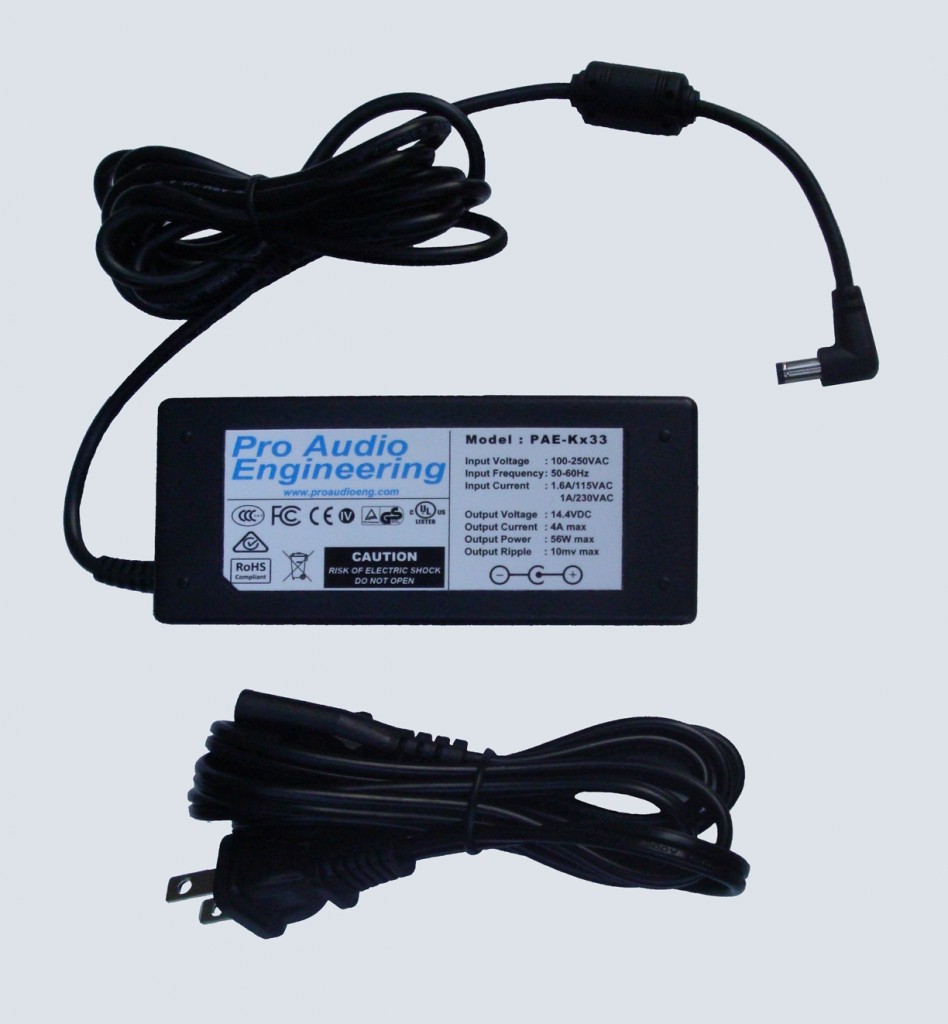
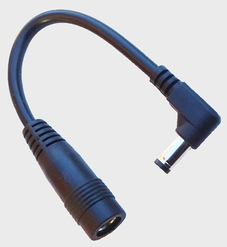
This is a specially priced combo of the PAE-Kx33 Low-RFI Power Supply plus 33-140 5.5mm x 2.5mm adapter for the IC-705@groups.io members included at no extra charge.
One piece of kit necessary for portable operation which has been elusive until now is a quality light-weight AC power supply. The PAE-Kx33 is the first compact, lightweight AC-line operated switching power supply specifically designed to perform at the level required by modern HF transceivers like the IC-705. When operating portable or traveling it is necessary to have a small, light power supply to either operate the rig or charge the batteries. Linear supplies can be very RF quiet, however dragging around a mains-powered 56 watt linear supply capable of a true 4A 14VDC output is a problem, they are too big and heavy for truly portable use. Check out the size, weight and cost of just the 50 or 60Hz 56VA transformer some time!
The PAE-Kx33 was designed specifically to address all of these specific concerns of the HF rig owner, and features:
- Hundreds already in use by IC-705 owners with complete satisfaction.
- Less RFI than any other switcher tested (see Test Results).
- Innovative switching topology to minimize RF interference and optimize efficiency.
- Extensive input and output filtering to ensure absolute minimum conducted and radiated RF.
- Less than a pound weight including AC cord to maximize portability.
- DC output is nominally 14.2V (see Specifications) at up to 4A.
- Works perfectly with the Icom IC-705 with the included PAE 33-140 5.5mm x 2.5mm adapter.
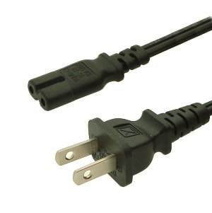
- Supplied with standard US AC cordset (see Specifications for details).
- Lower noise and more output current capacity = better value than both competing and more expensive supplies.
- In addition to 100% testing at the factory, every unit is tested for no and full load voltage and RF spectral output immediately before shipping to you.
Input Voltage: 100VAC to 240VAC.
Input Current: 1.6A peak at turn-on, 0.7A max at 100VAC full-load, 0.3A max at 240VAC full-load.
Input Frequency: 50-60Hz
Output Voltage (+/- 0.1V)@ plug: 14.4VDC at no load, 14.2VDC at 0.2A load, 14.0VDC at 3.5A load.
Output Current: 4A maximum.
Maximum ripple: 10mV.
Efficiency 82% minimum @ => 200ma load.
Protection: over-voltage, over-current, over-temperature, short-circuit.
MBTF: >50,000 hours.
Approvals: UL, FCC GS, TUV, CE, PSE, KC, SAA, CCC
Dimensions (excluding cables): 2″ x 1.25″ x 4.5″ (50mm x 32mm x 114mm)
Cable Lengths: AC cordset – 60″ (1.5M), DC supply cable – 80″ (2M)
Weight: supply: 9.3oz (264G), AC cord: 3oz (85G), total: 12.3oz (349G)
Warranty: 1 year from date of purchase. Read all Warranty details here.
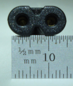
The PAE-Kx33 AC Power Supply has a standard 2-pin figure-8 AC input jack commonly designated an IEC 60320-C7, or merely C7 jack, and is supplied world-wide with US standard 2-prong NEMA 1-15P to figure-8 C7 2-pin AC line cord:
Due to the multiplicity of different AC plugs worldwide, we cannot stock other cordsets.
Adapters are readily available worldwide to fit the supplied cordset. Alternatively the purchaser can find a standard figure-8 2-pin cordset with the correct plug for their region.
The supplied cordset can also be modified by attaching the correct plug for the region.
There are several routes by which an AC line operated power supply can add noise to your transceiver: by conducting harmonics of the switching supply itself directly to the DC power jack, by conducting AC line noise to the DC power jack, or radiating switching noise from either the AC or DC power supply cables to the antenna/feedline. There is also a possible increase in the noise floor due to coupling with the AC line which is not necessarily added noise; it is actual signal increase of band noise due to increased antenna efficiency thanks to the ground counterpoise of the AC wiring. This effect is more pronounced on 160M and 80M, where many antenna counterpoises are relatively high impedance compared to the AC distribution system.
In order to quantify these effects we tested the new PAE-Kx33 along with several popular small switching supplies, a large linear supply and a large AGM (Absorbed Gas Mat) lead-acid battery. The switching supplies tested were all supplies commonly used in the ham community for QRP rig powering, and were suggested by fellow hams.
The test equipment used:
HP 34401A DVM for DC voltage measurements.
HP400EL AC RMS Voltmeter for RMS ripple measurements.
HP4263B LCR Meter to test AC input to DC output capacitance @ 100KHz.
Tektronix 2465 350MHz oscilloscope.
Tektronix 2712 Spectrum Analyzer for AC ripple spectrum measurements.
An Elecraft KX3 HF Transceiver was used as the test transceiver.
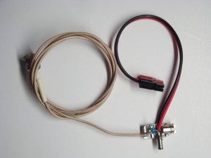
The measurements were taken directly from the KX3’s DC power jack with a small DC power splitter PCB. The AC output was fed by three paralleled 0.1uF XR7 capacitors (DC-blocking 10KHz HP filter into 50Ω) coupling the DC positive voltage to a 3′ piece of 50Ω RG-393 for the AC measurements. Both the Tek scope and spectrum analyzer were then terminated in 50Ω to reduce overshoot and ringing. Here is an image of the DC power sampling test jig:
In order to quantify the quality of the DC power output we tested for these parameters:
1) DC voltage, KX3 off.
2) DC voltage, KX3 in receive.
3) DC voltage, KX3 in transmit @ 10watts.
4) Capacitance from the AC line to the DC output ground. The lower the capacitance the less AC power line noise is conducted to the KX3.
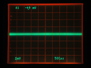
5) Ripple P-P amplitude as viewed on a connected directly to the KX3’s DC power jack. Note the vertical scale which was changed to optimally view the waveform. The lower the ripple, the less noise is conducted into the KX3.
6) The ripple RMS voltage , 10MHz BW.
7) Spectral capture of the increase in RF from 10KHz to 10MHz as compared to using an external battery.
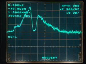
The Vertical Scale is 10dB/division, and it has been set so that the top line is -30dBm. The AGM battery and Astron linear supply spectra were straight-forward sweep captures. All of the switching supplies spectrum analyses were displayed as the difference between the spectrum when the KX3 was powered by the battery and the switcher being tested, normalized to the middle line of the screen. In other words, if the switcher was totally quiet, the trace would be a straight line at the middle of the screen. The greater a deviation from this the more noise energy the switcher generates compared to the battery. We did this because as you will see, when powered by a battery the KX3 passes RF from its internal circuitry to the DC power jack. Because of this even a perfectly quiet supply would show some RF at the DC power jack. Since we were trying to see how quiet these switching supplies were relative to the battery, the displayed spectra is normalized to the battery’s receive spectra with an algebraic C=A-B analyzer function, C being the differential sweeps shown here, A being the raw spectra of the switchers, and B being the spectrum of the KX3 on a battery.
The Horizontal Scale is linear frequency and it is set to 1MHz/division, so the left most vertical line is 0Hz, the center line is 5MHz, and the rightmost line is 10MHz.
When looking at these spectra, keep in mind the majority of the ripple in the output of each supply is at the switching fundamental frequency, which for all the supplies tested is between 20kHz and 100kHz. This places the spike associated with the fundamental too close to 0Hz to be seen in the screen shots below. Since it is not the fundamental but the harmonics and switching edge ΔV/ΔT spectra which wreak havoc with our HF ham bands, we set up to analyze the harmonics. The sweep is limited to 10MHz, since the majority of interference caused by switching power supplies is below that frequency. 10MHz is high enough to capture up to the 333rd harmonic of a 30KHz supply, or 99th harmonic of a 100KHz supply.
Although most of these switching supplies show an increase in output ripple at the higher current drawn by the KX3 in transmit, this is not usually a problem, since the receiver is muted. It can however, be a problem in a multi-operator contest or operation such as a dxpedition. To check this out we took a spectrum analysis from the battery with the KX3 in transmit @ 10W, drawing ~2.5A. This spectrum was then subtracted from each supplies individual spectra in the same manner as the receive testing, and the difference is displayed for each supply, normalized to the vertical center of the screen.
Important notes:
The DC voltages stated are measured at the DC power jack of a KX3, not read from the internal KX3 voltmeter, which reads several tenths of a volt lower depending on current.
When reviewing the test results pay attention to the scaling!
The oscilloscope sensitivity was set differently for each power supply in order to show detail about the ripple of that supply.
The spectrum analyzer settings were straight captures for the battery and linear supply, and differential captures (read the “Testing” tab) for all the switchers, with the display normalized to the vertical center of the screen. A perfectly quiet supply would be a straight line at the center of the screen which is ~-95dBm.
Powersonic PS12180 AGM Lead-Acid Battery
DC Voltage no load: 13.1V
DC Voltage receive: 13.0V@0.2A
DC Voltage transmit: 12.8V@2.5A
AC line to DC output capacitance: N/A
Maximum ripple amplitude: <200uVp-p
Ripple+noise RMS voltage (10MHz BW): <0.25mV
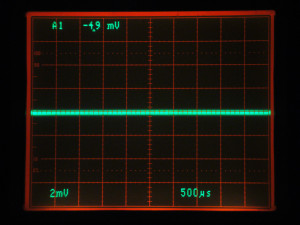
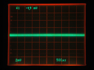
Powersonic AGM battery noise, the left image is with KX3 off, the right image is KX3 in receive drawing 0.2A. With the KX3 off, there is <400uV noise, which is the baseline of the test setup, and with the KX3 in receive the noise increases to ~800uV of noise. The KX3 receive noise is RF from internal circuitry bleeding back onto the DC power input line. This is an extremely low level and would most likely be undetectable on other equipment connected to the same supply.
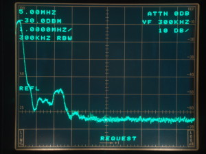
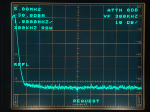
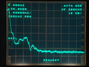
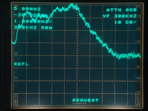
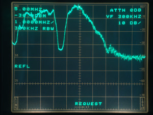
Powersonic AGM battery spectrum analysis taken at the KX3’s DC power jack, the left image is with KX3 off, the right image is KX3 in receive drawing 0.2A. . The RF present is very low-level with a broad maxima of -78dBm around 2-2.5MHz, and comes from the KX3’s internal circuitry. This spectrum was our baseline, and the spectrum which was subtracted from each of the line-operated supply’s spectra in order to get the true added noise from each supply. The noise floor of the KX3 when powered by the Powersonic AGM was our baseline for comparison with the other supplies. We are in an area with relatively high RF interference, so we do not report absolute noise floor levels when hooked to an antenna.
Astron RS-50M Linear Power Supply
DC Voltage no load: 13.2V
DC Voltage receive: 13.1V@0.2A
DC Voltage transmit: 13.0@2.5A
AC line to DC output capacitance: 1500pF
Maximum ripple amplitude: 5mVp-p
Ripple+noise RMS voltage (10MHz BW): 0.8mV
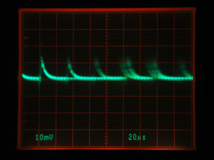
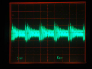
Astron linear power supply noise at the DC power jack, KX3 in receive drawing 0.2A. The average ripple is very low, with intermittent spikes which were difficult to capture with the scope photo, most likely due to AC line coupled energy.
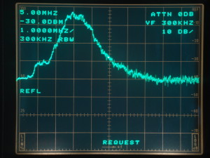
Astron linear power supply spectrum analysis taken at the KX3’s DC power jack in receive, KX3 drawing 0.2A. As with operating off the battery, there are no outstanding spurs, but the noise level from 500KHz to 2MHz is about 6dB higher than that of the KX3 powered by the AGM battery. This is probably due to coupling of power-line carried RF. We did not perform a differential spectrum analysis of the Astron vs. the battery. There was no perceptable change in the noise floor compared to using the Powersonic AGM battery. Any additional noise with increased power draw would most likely be line harmonics which are below the bottom limit of the analyzer, so we did not perform a transmit spectrum analysis.
PAE-Kx33 Switching Power Supply
DC Voltage no load: 14.4V
DC Voltage receive: 14.2V@0.2A
DC Voltage transmit: 14.0V@2.5A
AC line to DC output capacitance: <100pF
Maximum ripple amplitude: 4mVp-p
Ripple+noise RMS voltage (10MHz BW): 0.95mV
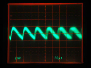
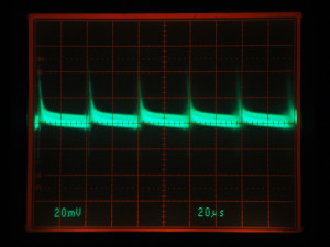
PAE-Kx33 switching supply, KX3 in receive drawing 0.2A, the fundamental ripple was ~4mVp-p at ~27KHz. Note the lack of any sharp switching transients. Switching device recovery is well damped. The ripple peak-to-peak as well as RMS amplitude is the lowest of all switching supplies tested. The ripple waveform is closest to a sine wave, and it’s peak-to-peak to RMS ratio is ~3.6:1. A sine wave is 2.8:1.
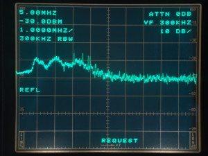
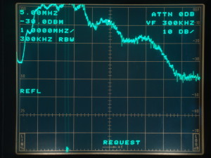
PAE-Kx33 switching supply spectrum analysis, KX3 in receive drawing 0.2A. RF output is lower than -80dBm. Comparing it against that of the battery shows one difference: the small broad rise from 1-4MHz of ~6-12dB relative to the battery, and a few spurs which were not audible in the KX3. Listening to 80M through 6M no increase in noise was heard relative to powering with the battery. In general the output spectrum is extremely clean, and 20dB lower than the next best switching power supply tested.
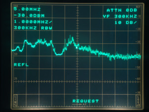
PAE-Kx33 switching power supply spectrum analysis, KX3 in transmit @10W drawing 2.5A. The output impedance of the PAE-Kx33 is extremely low from DC through 5MHz, so the 3.510 level superimposed on the DC line by the KX3 is almost identical to the performance of the battery or linear supply. The average supply noise level remained relatively constant compared to the PAE-Kx33 at 0.2A. This supply will be a good neighbor in a multi-op environment.
MeanWell GSM60A15-P1J Switching Power Supply
DC Voltage no load: 15.0V
DC Voltage receive: 14.8V@0.2A
DC Voltage transmit: 14.5@2.5A
AC line to DC output capacitance: ~500pF
Maximum ripple amplitude: 80mVp-p
Ripple+noise RMS voltage (10MHz BW): 2.7mV
MeanWell switching power supply noise at the DC power jack, KX3 in receive drawing 0.2A. the fundamental ripple was ~80mV p-p at ~100KHz.
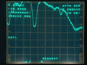
MeanWell switching power supply spectrum analysis, KX3 in receive drawing 0.2A. The average supply noise level is 40dB higher than the battery supply from 1 to 3.5MHz, and gradually drops from there. Listening to the KX3 while it was powered by this supply showed a marked increase in a cyclically changing scratchy noise floor on 160M and 80M.
MeanWell switching power supply spectrum analysis, KX3 in transmit @10W drawing 2.5A. The transmit test frequency was 3.510MHz. Note the fundamental superimposed on the DC power line with this supply. If the impedance of the supply at 3.510MHz was low, this part of the trace would have dropped down to the center line. Instead it is 8dB above. The average supply noise level increased another 10dB relative to the MeanWell at 0.2A.
Ktec KSAS065 Switching Power Supply
DC Voltage no load: 14.2V
DC Voltage receive: 14.0V@0.2A
DC Voltage transmit: 13.5@2.5A
AC line to DC output capacitance: ~350pF
Maximum ripple amplitude: 30mVp-p
Ripple+noise RMS voltage (10MHz BW): 3mV
Ktec switching power supply noise at the DC power jack, KX3 in receive drawing 0.2A. The fundamental ripple was ~30mVp-p at ~31KHz. It is hard to see the sharp leading edge spikes in the waveform which consititutes 1/3 of the amplitude.
Ktec switching power supply spectrum analysis, KX3 in receive drawing 0.2A. This supply outputs between 20dB and 30dB of energy between 1 and 5 MHz relative to the battery, slowly decreasing as the frequency rises. Listening to the KX3 there were numerous single-frequency spurs on 160, 80, and 40M which changed frequency as the power draw varied.
Ktec switching power supply spectrum analysis, KX3 in transmit @10W drawing 2.5A. The impedance of this supply at 3.510MHz is better than that of the MeanWell, but still allows the level to rise by 6dB. The average supply noise level remained relatively constant compared to the Ktec at 0.2A.
MFJ 4103 Switching Power Supply
DC Voltage no load: 14.2V
DC Voltage receive: 14.1V@0.2A
DC Voltage transmit: 13.8@2.5A
AC line to DC output capacitance: 1000pF
Maximum ripple amplitude: 15mVp-p
Ripple+noise RMS voltage (10MHz BW): 1.9mV
MFJ switching supply, KX3 in receive drawing 0.2A, the fundamental ripple was ~ 30mVp-p of 2.6MHz modulated at 100KHz. The MFJ had the highest switching frequency of all the switching power supplies tested. Although higher frequencies can mean a smaller, lighter supply, the MFJ was the largest supply tested, and this high a switching frequency certainly poses a challenge to the design of the output filter.
MFJ switching power supply spectrum analysis, KX3 in receive drawing 0.2A. Compared to the battery the MFJ supply had a broad peak of energy centered at 3MHz which reached 36dB relative to the battery at its peak. The MFJ did not have any audible spurs, however an increase in background noise was observed on 80M.
MFJ switching power supply spectrum analysis, KX3 in transmit @10W drawing 2.5A. The impedance of the MFJ at 3.510MHz is pretty low compared to the MeanWell and Ktec, and allows the signal to be 2dB above baseline. The average supply noise level remained relatively constant compared to the MFJ at 0.2A.
AC Power Supplies and RFI
When powering a 12VDC receiver from an AC line power source you may find the receive noise floor becomes contaminated with noise of various sorts which are not present when powered by a battery and isolated from the AC power system. It is tempting to believe that all of the additional noise originates from within the power supply, but this is often not the case. It is also a common misconception that all linear power supplies powered from the AC mains are as quiet as batteries, and that all switching power supplies are noisy. The truth is more complicated and is due to the multiple routes by which RF Interference (RFI) can be induced into a receiver.
The main routes for RFI are:
1: Transverse or Differential-mode conduction of RF ripple superimposed on the DC power supply output can introduce RFI into the equipment being powered. It is critical for the designer of a supply to resolve this source of noise inside the supply as it can cause radiated RFI if allowed to propagate on the DC power cord. We specifically designed the Kx33 to have extremely low RF ripple on the DC output and to date have not had any of this type of RFI reported.
2: Common-mode currents from the antenna system can use the coax feedline shield as a counterpoise and conduct through the rig, then through the power supply DC cable and power supply to the AC line. Whether this coupling introduces noise depends on two main factors:
a. Balance and common-mode potential of the antenna system.
If the antenna system has a current imbalance between the two halves of a dipole, or between the main radiator and counterpoise as most end-fed antennas do, the imbalance current flows down the outside of the coax feedline shield turning it into an active part of the antenna system. This will
affect the antenna pattern in receive and transmit as well as allow the feedline to receive ambient noise. The rig chassis, the power supply, and AC mains are then all in a series path for these common-mode currents making them an active part of the antenna system as well. Inserting a common-mode choke in the antenna feedline at the antenna feedpoint is the best
way to reduce or eliminate this common-mode current flow. Choking the DC power lead is a second-best solution. An excellent reference on this subject can be found on K9YC’s site: http://audiosystemsgroup.com/RFI-Ham.pdf
b. The AC input to DC output impedance of the power supply.
All AC line powered supplies have capacitive coupling between the AC line and the DC output. This can be a path for RF energy to take if a difference in potential exists between the two. When using a linear supply the instantaneous input to output impedance will be modulated at the AC line frequency, leading to the hum commonly heard in older single-conversion receivers. When using a switching supply the coupling can be modulated
by the dynamic impedance of the switching action and can cause RFI. Measurements taken of many power supplies by PAE show linear and switching supplies offer ~1000 pF of capacitive coupling to the AC input on average. At ~70 pF the Kx33 greatly minimizes this coupling and the magnitude of this common-mode RFI current. This makes choking common-mode currents much easier with the Kx33 than with other power supplies. For cases where an antenna system may present common mode potential we include a Fair-Rite mix 31 Snap-It core which can be used to make a commom-mode choke by winding the DC output cable of the Kx33 through the core 3-4 turns. This will effectively increase the common-mode impedance through the Kx33 by 800 to 1000 ohms @10 MHz, effectively minimizing this current path through the supply. If additional ferrite products are desired we offer a range of Fair-Rite Ferrite Clamp-On and toroid cores at low cost to our customers at:
https://proaudioeng.com/fair-rite-ferrites/
We made the decision not to integrate a large ferrite choke like the included Snap-It core inside the Kx33 in order to minimize size and weight. For 99% of all users, the RFI performance of the Kx33 itself will be sufficient, and if additional common-mode choking is required the additional core can be employed.
3) Radiated RFI from many sources can be picked up by the antenna system and appears as a signal in the receiver. In a well-designed supply like the PAE-Kx33, the external fields from the high-current PCB loop between the switching devices and transformer, as well as the fields of the transformer itself are extremely small. In order to minimize the pickup of any radiated RFI we recommend placing the supply the full length of the DC supply cord away from the rig.
Out of >5000 customers less than 0.1% have experienced any additional RFI caused by proper use of the Kx33. Of those that have, addition of the ferrite core has remediated the noise. We are sure you will be happy with the Kx33 or we will refund both your purchase and shipping costs, so there is no risk other than a small amount of your time evaluating it.

