
While refurbishing my Drake Twins, an early serial number R-4B and T-4XB pair, I ran into difficulty with the R-4B PTO. Mechanically it was fine after some cleaning, but suffered from a thermal intermittent. From a cold turn-on, the PTO frequency was highly variable with line voltage. I had the R-4B on a Variac and I could change the frequency a few KHz by varying the line voltage between 110 V and 125 V, which is unacceptable stability. This meant as AC loads turned on and off in my house the frequency would bobble around in a erratic fashion.
After 10 minutes or so the frequency would suddenly stabilize and be relatively immune to line voltage as it should be, with only a few Hz shift induced by varying the AC input from 110 to 125 V.
I measured the voltage at the PTO B+ input and it would initially drop to 9 V which meant the Zener was out of regulation. The voltage at this point would suddenly increase to 12 V when it warmed up, putting the Zener back in regulation. This said to me something internally was drawing excessive current until it came to operating temperature. I installed a new Zener for D9, but that did not fix the problem.
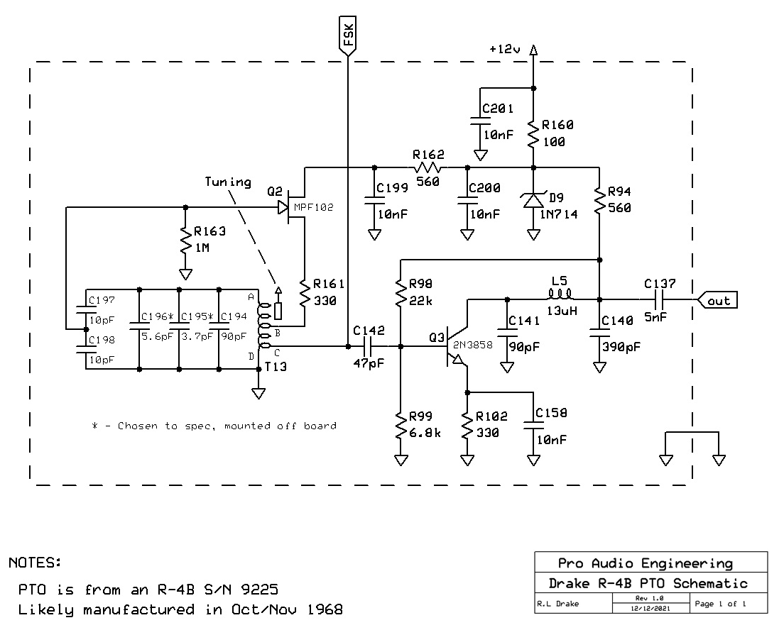
Along the way I found some excellent Drake info from many sources, including the helpful package of files put together by Garey Barrell / K4OAH (SK). Unfortunately I had been unable to find PCB layouts of the PTO, and as helpful as the Drake PTO schematic was, it is unintuitive from a signal-flow perspective and difficult to follow, so I drafted one more to my way of thinking:
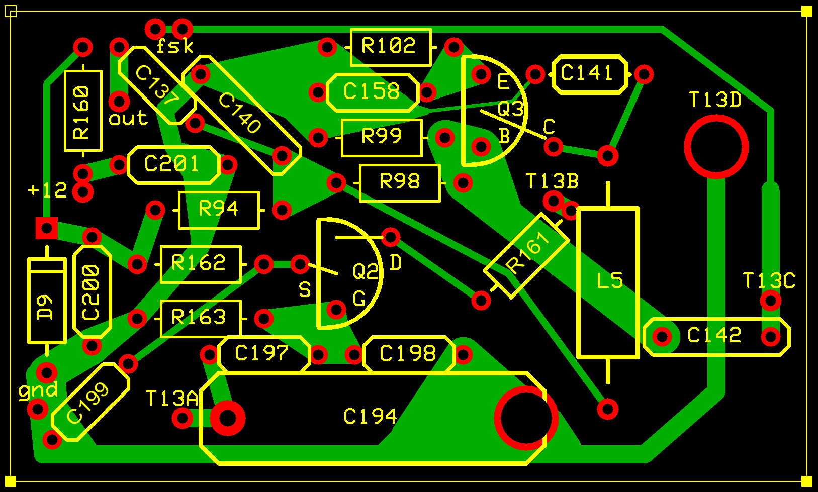
Once I had removed the PTO and began to examine the PCB I realized I needed a PCB layout as well, and several hours of searching the internet did not turn one up. In the layouts below the PTO coil T13’s four connections are labeled A, B, C and D and correlate with the schematic’s references:
Component Side:
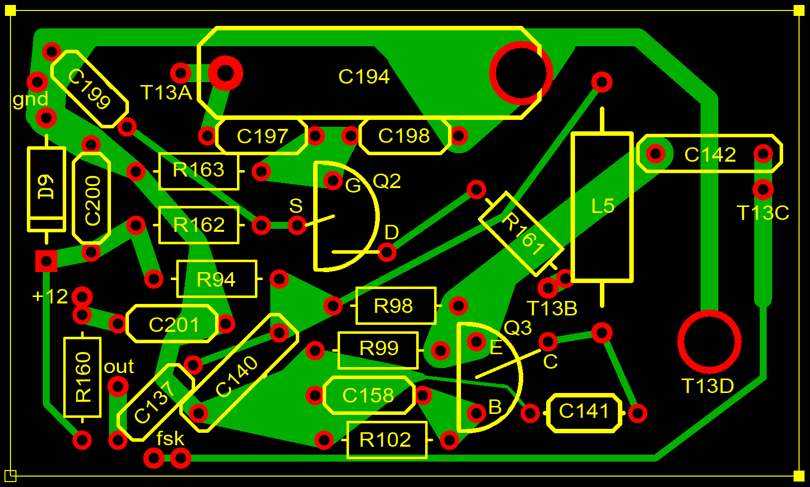
Foil Side:
I hope the time spent drafting these layouts will assist some other soul attempting a PTO repair!
I replaced the four 0.01 uF 25 V disc bypass caps (C158, 199, 200, 201) with new 50 V Vishay ceramic caps, and also replaced the 47 pF inter-stage coupling cap C142 with a 1KV C0G Vishay ceramic cap. The higher voltage caps show less modulation of capacitance with voltage. I reassembled the PTO and after several cold to hot cycles, it seems the problem has been fixed. On to the T-4XB PTO!
THANK YOU!!! Just starting on a R4B receiver PTO that drifts more than the desert sand, back and forth constantly. I will be replacing FET with a J113 along with the buffer transistor
and caps you mention, also the zener for sure.. Your help here is SUPER. Just too bad Garey didn’t have this info on his CD’s that are fantastic.